A Performance Study of a Cross-flow Air Turbine Utilizing an Orifice for OWC WEC
Abstract
A cross-flow air turbine is a candidate for usage of a self-starting turbine due to its characteristic, which are high coefficient at a low tip speed ratio, excellent stability and low noise. With its characteristics this turbine can be more suitable for OWCs (Oscillating Water Columns) which require low noise and high maintenance compared to typical commercialized air turbines such as Wells and impulse turbine. The investigation of a cross-flow air turbine, in this research, for OWC wave energy converter have been undertaken. First, a numerical analysis of the full-scaled turbine by CFD have been conducted in order to acquire its performance characteristics in various range of the flow rate with different rotational speed of the rotor. Model scale analysis was then proposed to design and compare with experimental model, and 1/16 model scale was determined. In addition, an orifice plate as substitute was adopted not only to simulate the behavior of the turbine by numerical analysis and experiment but also to verify the CFD result by the experiment result. The size of the orifice plate was determined by matching between the pressure drop across the upstream and downstream of the turbine and orifice. With the entire result, the comparative study between orifice plates and turbine simulation have been proposed.
Keywords:
Cross-flow Air Turbine, Orifice, OWC, Wave Energy키워드:
공기 횡류 터빈, 오리피스, 진동수주형 파력발전장치, 파력 에너지1. Introduction
Ocean energy which includes tidal energy, ocean thermal energy conversion, wave energy and other energy currents, hold an enormous amount of untapped energy that, if exploited extensively, have a potential for contributing significantly to the electricity supply of countries facing the sea.(1) The most commercially viable form of resources researched so far are ocean currents and waves which are both on the progress of developing.(2) It is estimated that the total amount of marine and tidal currents energy contain about 5TW,(3) the scale of the global total power consumption. In addition, approximately 8,000 to 80,000 TWh/yr of wave energy can be obtained theoretically which provide 15 to 20 times more viable energy per square meter than other type of renewable energy such as solar and wind.(4) One of the closet wave energy conversion technologies to the commercial stage are Oscillating water columns (OWCs). OWC device consists of a chamber structure and turbine, connected to a generator. Oncoming waves from sea make the free surface of the fluid in the chamber to oscillate and causes a changing in air pressure within the chamber driving the volume of air through the bi-directional turbine at the opening of the device.(5) The turbine is connected to a generator so that mechanical motion from the turbine provides the production of electrical energy.
One of the significant consideration for the OWC wave devices is the air compressibility in the section of air chamber due to its large volumetric space and high air chamber pressure in the typical OWC devices. Sarmento et al.(6) have introduced a linearized formula in terms of the flow rate through the PTO system, based on the assumption of an isentropic flow. Sheng et al.(7) have researched the air compressibility by formulating a full thermodynamic differential equation for the volumetric flow rate through the PTO system and in the chamber as well, and the validation of the proposed method has been processed using experimental data.(8) With the calibrated relationship between the flow rate and pressure through the PTO system, the complicated analysis of the PTO process could be simplified. Thus, it induces the simplified calculation of the power conversion process from the PTO. In this research, the simplified formula of the relation between the pressure and flow rate through the PTO system have been adopted.
The main characteristic of the cross-flow turbine is its relatively wide range of operating range from low to medium head. Its significant advantage is that the turbine provides the similar performance and efficiency for different flow rates. However, a cross-flow type turbine have normally been applied as a water turbine in hydropower system rather than as air turbines in wave energy converters. Only a few studies have handled with the cross-flow turbine for the self-rectifying air turbines which can be used for wave energy conversion. Mockmore and Merryfield(9)introduced the design theory of the cross-flow turbine with all design factors such as blade angle, spacing and number according to different flow conditions. Fukutomi et al.(10) conducted the numerical calculation and experiment of the flow through the cross-flow turbine nozzle and provided the design parameters for the shape of nozzle, and its significant design parameters are nozzle entry arc, throat width and upper wall shape. One research of the self-rectifying cross-flow air turbine for wave energy conversion was induced by Akabane et al.(11) The test performed under steady flow conditions with three kinds of turbine having 30 blades, 200mm diameter and 100mm width that produced the maximum efficiency as 29%. Although the result seems that the turbine is inferior to other types of air turbines such as Wells and Impulse turbine, it is inappropriate to compared the single cross-flow turbine to the other turbines having extra installations such as guide vanes which increase the its performance. The cross-flow air turbine have a potential to be more suitable for OWC wave energy converter with its benefits, wide range of operating range with relatively constant performance.(12)
The aim of this research is to investigate the cross-flow air turbine for OWC wave energy converter. The cross-flow air turbine have not been applied as an air turbine for OWC wave energy converter since it has a potential competitiveness of air turbine for OWCs compared to other types of air turbines. First, the performance analysis for the cross-flow air turbine have been processed to obtain the performance of the turbine in various range of the flow rate with different rotational speed of the blade. After then, the orifice plate as substitute for turbine damping effects have numerically studied by CFD. In addition, the comparative study between CFD analysis and experiment was proposed for verification of CFD result.
2. Methodology
2.1 CFD analysis of a cross-flow air turbine
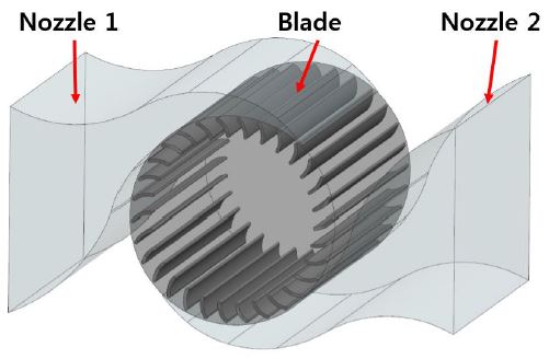
A direct method to calculate the general dimension and flow parameters for the runner and nozzle section was utilized referring to Mockmore et al.(9) and Fukutomi et al.(10) respectively. The designed crossflow air turbine is illustrated in Fig. 1 and the design parameters are described in Table 1. The cross-flow turbine in its simplest form consists of a nozzle and a runner section. The induced air flow due to increasing wave level moves through the rectangular crosssection nozzle and flows into the runner. When the wave level is decreased, the air flow from the atmosphere passes through the symmetric shape of nozzle and enters the runner again. Thus, the circulating air flow is continuously moving through the nozzles and runner section that rotate the blade in uni-direction.
CFD simulations of the cross-flow turbine in 3D steady state and transient state were processed using the commercial CFD code ANSYS CFX 14.0. The single domain of the cross-flow air turbine excluding OWC chamber and wave elevation was determined for simplicity of analysis. The full scale of the turbine was adopted for steady state simulation to acquire real performance characteristics of the turbine under real air flow rate conditions. The transient simulation was conducted as 1/16 scale to verify the simulation result by comparing with the experiment result. The mesh comprising fine hexahedral grids, shown in Fig. 2, was generated by ANSYS ICEM CFD so that the high accuracy of analysis results are obtained. The simulations were processed with SST turbulence model. The boundary condition, shown in Fig. 3, for the steady state simulation was set with different rotational speed of 16, 32, 48, 64 rpm and uni-directional inlet air velocity from 2 m/s to 40 m/s, calculated using the design wave elevation and periods, for full scale conditions. In addition, the bi-directional flow having sinusoidal pattern, calculated using the linear wave theory with 0.125m wave height and 0.125~2 sec periods, allows the volume of air induced due to wave motion to pass through the turbine for the transient simulation. The single air phase in boundary condition was used which allows only air to move through the turbine. General Grid Interface (GGI) method was applied for the mesh connection between each parts with the interface.
Time-series data is cyclical and it is represented into one phase single time-series by a phase averaging method. The primary aim of the phase averaging is not only to obtain smooth result from unstable data from simulation and experiment but also to represent all data, which have different time steps, in one single phase so that all data can be compared in same time range. The time of the time-series data is converted to nondimensionalized by substituting the actual time with a non-dimensional phase (t/T). The time series is divided into segments of repeating cycles with zero-up-crossing. Then, the phase of the data points is allocated by subtracting the previous adjacent zero-up-crossing time and dividing by the cycle period(13) as shown in Equation (1), where time of zero crossing of immediate cycle (Tzero), time of zero-crossing of end of immediate cycle (Tzero+1), measured time (T measured) and 0 ≤ t/T < 1.
| (1) |
2.2 Validation of an orifice for turbine damping effects
The energy conversion process in OWC chamber produce a pressure drop across the chamber, which causes the oscillating amplitude of the water column. This in turn generates the cycle repeats and the pressure drops across the air turbine, which is the PTO device. However, it is difficult to install and investigate the model-scaled air turbine in the experiment due to the complexity of its geometric configuration and relatively high rotational speed(12) under small scale (1/16). Thus, the orifice plate is considered as a substitute of the air turbine for the investigation of similar behavior of pressure drop effects. In this section, the analysis of the turbine damping effects with the orifice plates for predicting the chamber performance by CFD and experiment will be discussed.
The flow rate through an orifice was determined by calculation of the equations due to its difficulty of calibrating the oscillating flow rate, which contains the air compressibility. It is assumed that the air inside the chamber is isentropic for which a state equation for the open system can be represented in Equation (2), where absolute chamber pressure (pc), chamber density (ρc), and specific heat ratio of the air (γ=1.4).
| (2) |
Linearized expression for the density of air inside the chamber can be illustrated(14) as following Equation (3),
| (3) |
and
| (4) |
A simplified expression of the air flow rate through the PTO system(15) can be described as depicted in Equation (5), where initial chamber volume (V0). The second term in the RHS of the equation is expressed as a modification due to the air compressibility.(14) This equation was adopted to calculate the flow rate through an orifice for both inflow and outflow due to its air compressibility and its simplicity, which can be easily applied in both inflow and outflow.
| (5) |
The dimensions of the orifice plates were designed according to EN ISO standard.(13) The diameter ratio of the orifice, β=d/D, where d=orifice diameter and D=nozzle diameter, was calculated based on the cross-sectional area of the turbine nozzle.(12) Various orifice plates with different orifice ratio were tested to obtain similar behavior of turbine damping effects, and the size of the orifice is 0.3D to 0.5D.
The entire domain of the orifice plate have same model scale as the 1/16 scaled turbine, and it was analyzed excluding the OWC chamber and wave motion as well as depicted in Fig. 5. The mesh comprising fine hexahedral grids with 1.51 x 10⁶ nodes was generated as shown in Fig. 4. The transient type of simulation was applied so that same bi-directional sinusoidal flow can pass through the orifice, which generate the damping effects. The same condition of sinusoidal air flow as the turbine was adopted in order to compare the result under same flow condition.
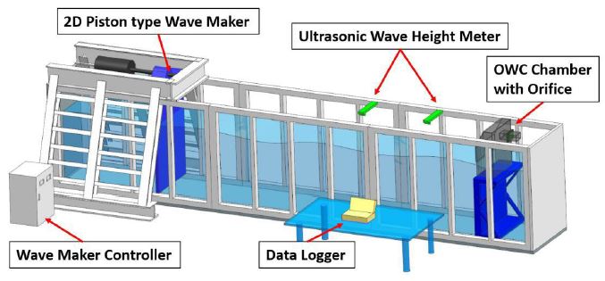
The experiment was designed and conducted at an experiment facility of Korea Maritime and Ocean University to validate the result of CFD analysis by the experimental result, which represents a real flow behavior. To generate the turbine damping effect through the nozzle, the 1/16 scaled OWC chamber was adopted into the wave tank. The orifice plate as the turbine substitute was then installed inside the nozzle of the OWC chamber. The boundary conditions (wave heights and periods) to generate the same condition of bi-directional flow into the orifice were designed equally.
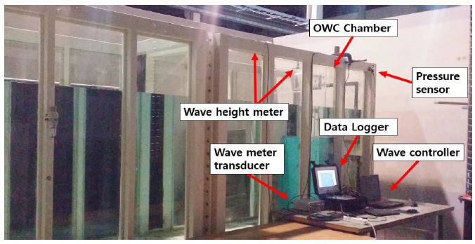
The orifice plates were installed at the nozzle of the OWC chamber as shown in Fig. 6. The OWC chamber installed in the wave tank which faces the oncoming wave, generated by the piston type wave maker. The OWC chamber model is composed of Acrylic material with its thickness of 10 mm so that the wave behavior can be observed. The design wave was fixed as 0.125 m with 1.25 to 2.0 sec of periods. The diameter ratio of the orifice plates (0.3D, 0.33D, 0.35D, 0.37D, 0.4D) were tested. The two ultrasonic wave height meters were installed on 1 m front of and at the top of the OWC chamber to measure the height of oncoming wave and inside the chamber respectively. With the measured wave height inside the chamber and period, the flow rate passing through the orifice were calculated using the equation (5).
3. Results and discussion
3.1 Cross-flow air turbine
The performance of the full-scaled cross-flow air turbine was acquired by CFD steady state simulation, and Fig. 8 depicts the performance curve by a dimensional analysis method.(17) The turbine was investigated by varying the rotational speed of blades (16, 32, 48 and 64 rpm for full scale) and the inlet air velocity (from 2 m/s to 40 m/s). The peak performance of the turbine was 0.587 at the rotational speed of 48 rpm and the inlet velocity of 12 m/s. All performance for different rotational speed of the turbine have relatively same tendency. When it comes to noise issue in turbine operation, the low rotational speed (16 rpm) of the turbine could be more suitable although the performance of 16 rpm is slightly less than the others. After the stall region, the performance curves tend to significantly drop, and it means that the operating range of the turbine is relatively narrow. The operating range of this turbine is positioned mainly between 0.2 to 0.8 flow coefficient, whereas typical Wells turbine and impulse turbine have 0 to 0.2 and over 0.6 respectively. From this result, it can be said that this cross-flow air turbine is able to operate effectively between 0.2 to 0.8 flow range which is not suitable for other turbines.
It is noted that the investigation of this turbine is the early stage of research, thus it needs to be improved by further modification of geometries or possible variables.
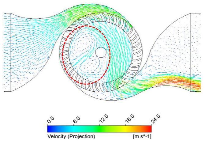
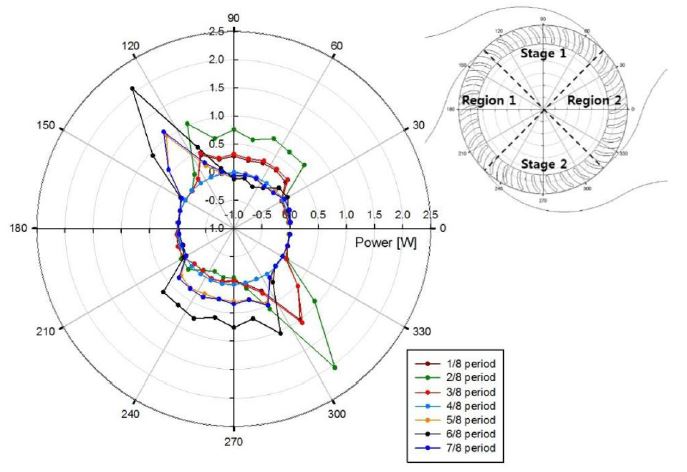
The analysis of 1/16 scaled turbine under bi-directional flow have been carried out by CFD transient simulation that both for investigation of flow behavior through the turbine and for validation of CFD result with an experimental data. Fig. 9 presents the bi-directional flow behavior through the turbine at 2/8 period of 1.25 sec, which the flow velocity through the blade is the highest. Fig. 10 indicates the power distribution on entire rotor domain. The divided power output was calculated by each torque of the runner blades during one cycle. Based on the center circle (zero), the outside lines represent the absorbed kinematic air energy by the rotor blades, and inner lines represent the energy loss due to turbulence and swirl of air at region 1 and 2 as shown in Fig. 9. It is shown that the power output was mainly captured at stage 1 for exhalation cycle and at stage 2 for inhalation cycle unlike power reduction and loss were observed in region 1 and 2. In addition, all different period have similar tendency of power distribution. The higher power output was acquired at shorter period as 1.25 sec, and the power amount was decreased as longer period.
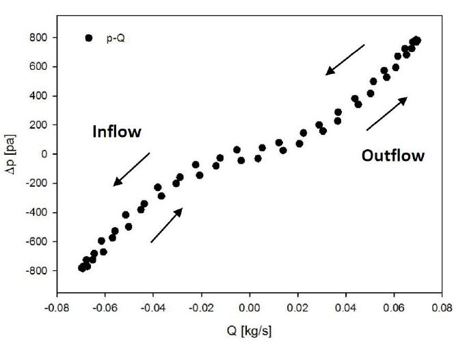
A relation between flow rate and pressure drop during one cycle can be obtained as a hysteresis loop with the phase averaging method as shown in Fig. 11. The hysteresis loop consists of exhalation and inhalation of the air flow. The right side of the graph represents an exhalation of an air and the left side depicts an air inhalation. The gap between an increasing and decreasing lines for both outflow and inflow occurred due to the change of air density by the different air acceleration. For short period, at 1.25 sec, an irregular behavior in the hysteresis loop was obtained due to its significant effect of air compressibility. In addition, the pressure drop between upstream and downstream of the turbine becomes smaller as an increase of period, decrease the flow rate.
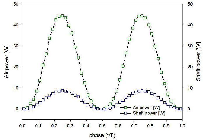
With the phase averaged data of pressure, flow rate and torque, an aerodynamic power and turbine’s shaft power were obtained as shown in Fig. 12. The air power represents the aerodynamic energy amount of incoming air, and the shaft power depicts the mechanical energy converted by the turbine. The feature of both air and shaft power graph have similar configuration as the torque graph. The averaged power output of air and shaft power was applied to calculate the averaged efficiency of the turbine performance during one cycle due to its varying data as time series. The summary of the turbine performance for different periods is illustrated in Table 2. All case have similar performance and the overall efficiency is around 23.6%. The maximum efficiency of the turbine was 25.7% at 2.0 period and 1000 rpm rotational speed. The producing power at 2.0 sec by the turbine was 3 times less than at 1.25 sec. Hence, from this result, this turbine is more suitable at the condition of shorter wave period to produce larger amount of energy even though the overall performance is slightly less than at long period. However, it must be noted that this performance result is close to theoretical result due to its linear wave theory, which produces linear motion of air flow with less turbulence into the turbine. This means that the turbine performance could be significantly decreased if this device is applied on real sea. Thus, further study for improvement of the device will be conducted.
3.2 Comparative study with an orifice
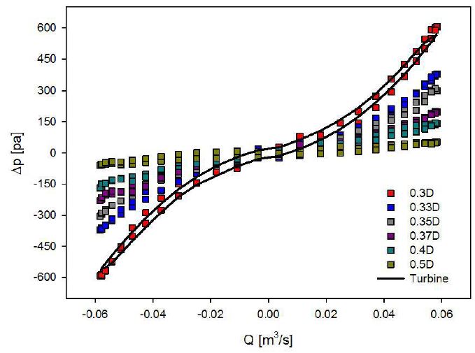
The numerical analysis of orifices having different dimension (0.3D to 0.5D) by CFD have been carried out under same bi-directional flow condition to find the orifice which can simulate similar damping effects of the turbine. The entire CFD result of the orifices and turbine at 1.5 sec wave period is depicted in Fig. 13. Varying the diameter ratio of the orifice at same bi-directional flow rate induced the different pressure drop across the upstream and downstream of the orifice in one cycle, and the smaller size of the orifice diameter caused the increase of the pressure drop across the orifice. It is indicated that the ratio 0.3D have a significantly closer fitting behavior to the turbine performance and a proper solidity as the turbine. With the 0.3D orifice, the turbine damping effects can be predicted, and it can be applied on further research of the turbine for both its verification and simplicity in study.
The experiment of orifice plate (0.3D to 0.4D) embedded in the OWC chamber was processed at the condition of 0.125 m wave height and 1.25 sec wave period (same condition as CFD simulation). The predicted performance of the orifice by CFD was compared with experimental result, and one of comparisons (0.3D orifice at 1.25 sec wave period and 0.125 m wave height) was shown in Fig. 14. With only the result, it was observed a relatively good agreement between CFD and experimental results that validates the methodology.
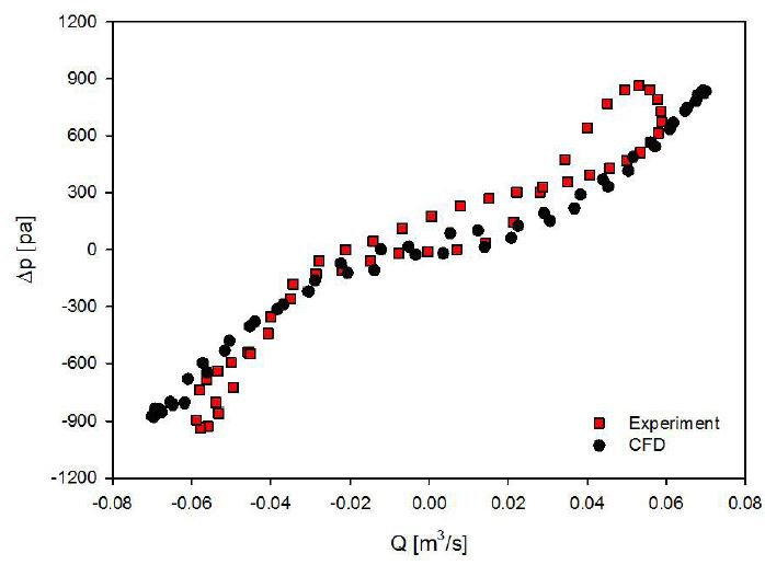
Validations of a orifice between CFD and experimental result (0.3D orifice, 1.25 sec and 0.125 m wave height)
The remarkable hysteresis loop for the chamber pressure and the air flow rate through an orifice was observed from the experimental result rather than from the CFD result due to relatively nonlinear motion of the air flow by wave into the chamber. More irregular feature during exhalation process than inhalation process was captured. The reason for this is than the air flow through the orifice during the exhalation process is pressurized and pushed to atmosphere by nonlinear motion of wave piston, whereas the incoming air from atmosphere is supplied with relatively constant atmospheric pressure. In addition, the shorter wave period inducing higher pressure inside the chamber gets more effect of air compressibility. It means that power loss in the air chamber can be captured at shorter period.
4. Conclusion
The paper presents the study of the cross-flow air turbine utilizing an orifice for OWC wave energy converter with CFD and experimental analysis. The cross-flow air turbine have a potential strengths such as a low speed of rotational speed at wider range of flow condition compared to other typical air turbines for OWCs. However, the research of this air turbine is an early stage of development, and it has significant tasks (relatively low performance) which should be settled in further study.
From the study, the following conclusions can be drawn as,
- ㆍThe highest performance efficiency of the turbine was 58.7% at the 48 rpm rotational speed and 12m/s air velocity under uni-directional flow condition.
- ㆍThe turbine is able to operate similar performance at lower rotational speed, and it can generate less noise during operation.
- ㆍ0.3D orifice can simulate similar damping effects of the turbine.
- ㆍRelatively good agreement between CFD and experimental results could be obtained by the validation.
- ㆍPower loss due to the air compressibility can more occur in shorter wave periods through the PTO (power-take off) system.
References
- Kang, H. G., Wata, J., and Lee, Y. H., (2016), “Numerical Analysis of Small-scale Cross-flow Air Turbine for OWC Wave Energy Converter by CFD”, Proceedings of The Korean Society for New and Renewable Energy Conference, p129.
-
Muetze, A., and Vining, J. G., (2006, October), “Ocean Wave Energy Conversion-a Survey”, In Conference Record of the 2006 IEEE Industry Applications Conference Forty-First IAS Annual Meeting, 3, p1410-1417, IEEE.
[https://doi.org/10.1109/ias.2006.256715]

- Richard Boud, (2003), “Status and Research and Development Priorities, Wave and Marine Accessed Energy”, UK Dept. of Trade and Industry (DTI), DTI Report # FES-R-132, AEAT Report # AEAT/ENV/ 1054, United Kingdom.
- Wavemill Energy Corp., “Electric power form ocean waves,” [Online], Available: http://www.wavemill.com.
- Kang, H. G., Wata, J., and Lee, Y. H., (2016), “A Study of a Cross-flow Air Turbine with Orifice for OWC Wave Energy Converter by CFD and Experiment”, 6th Asia-Pacific Forum on Renewable Enegy, p55.
-
Sarmento, A. J. N. A., Gato, L. M. C., and de O. Falcao, A. F., (1990), “Turbine Controlled Wave Energy Absorption by Oscillating Water Column Devices”, Ocean Engineering, 17, p481-497.
[https://doi.org/10.1016/0029-8018(90)90040-d]

-
SHENG, W., ALCORN, R., and LEWIS, A., (2013), “On Thermodynamics in the Primary Power Conversion of Oscillating Water Column Wave Energy Converters”, Journal of Renewable and Sustainable Energy, 5, p023105.
[https://doi.org/10.1063/1.4794750]

-
Sheng, W., Thiebaut, F., Babuchon, M., Brooks, J., Alcorn, R., and Lewis, A., (2013), “Investigation to Air Compressibility of Oscillating Water Column Wave Energy Converters”, Proceedings of the ASME 2013 32nd International Conference in Ocean, Offshore and Arctic Engineering, OMAE 2013, 9-14th June, 2012, Nantes, France.
[https://doi.org/10.1115/omae2013-10151]

- Mockmore, C. A., and Merryfield, Fred., (1949), “The Banki Water Turbine”, Engineering Experiment Station Oregon State System of Higher Education Oregon State College Corvallis.
-
FUKUTOMI, J., NAKASE, Y., and Watanabe, T., (1985), “A Numerical Method of Free Jet from a Cross-flow Turbine Nozzle”, Bulletin of JSME, 28(241), p1436-1440.
[https://doi.org/10.1299/jsme1958.28.1436]

- Akabane, M., Suzuki, H., and Yamauchi, K., (1984), “On the Cross Flow Turbine for Wave Power Plant”, In Proceedings of the 1st Symposium on Wave Energy Utilization in Japan.
- Kang, H. G., (2017), “A Study on the Performance of a Cross-flow Air Turbine Utilizing an Orifice for OWC Wave Energy Converter”, Masters Dissertation, Korea Maritime and Ocean University, Busan, Korea.
-
FLEMING, A., PENESIS, I., MACFARLANE, G., BOSE, N., and HUNTER, S., (2012), “Phase Averaging of the Velocity Fields in an Oscillating Water Column Using Splines”, Proceedings of the Institution of Mechanical Engineers, Part M: Journal of Engineering for the Maritime Environment, 226, p335-345.
[https://doi.org/10.1177/1475090212439826]

-
SHENG, W., ALCORN, R., and LEWIS, A., (2013), “On Thermodynamics in the Primary Power Conversion of Oscillating Water Column Wave Energy Converters”, Journal of Renewable and Sustainable Energy, 5, p023105.
[https://doi.org/10.1063/1.4794750]

-
SARMENTO, A. J., and FALCÃ, O, A. D. O., (1985), “Wave Generation by an Oscillating Surface-pressure and Its Application in Wave-energy Extraction”, Journal of Fluid Mechanics, 150, p467-485.
[https://doi.org/10.1017/s0022112085000234]

- ISO, E., (5167-2: 2003), “Measurement of Fluid Flow by Means of Pressure Differential Devices Inserted in Circular-Cross Section Conduits Running Full-Part”, 2.
- Falcao, AFO, And Gato, LMC, (2012), “8.05 Air turbines”, Comprehensive Renewable Energy, 8.
