Air Entrainment Flow Characteristics of Horizontal and Elbow Type Gate Pump-Sump Models
*Graduate school, Department of Mechanical Engineering, Mokpo National University**College of Mechanical and Electrical Engineering, Wenzhou University, China
***Soosung Engineering Co. Ltd
****Department of Mechanical Engineering, Institute of New and Renewable Energy Technology Research, Mokpo National University
Abstract
The gate pump has recently received considerable attention as a type of effective drainage equipment. Air can be easily inhaled by the suction pipe, which could cause damage to the pumping system. Therefore, to improve the hydraulic performance of the gate pump, the flow behavior of the pump, including the pump-sump, must be investigated. This study focused on the investigation of the air entrainment and water flow behavior in the horizontal and elbow gate pump-sump models using a computational fluid dynamics analysis. A three-dimensional fluid domain of the horizontal and elbow gate pump models was constructed. Subsequently, the commercial code of ANSYS CFX was adopted to conduct numerical simulations. The unsteady simulations of the two-phase flow (air and water) were performed using the shear stress transport turbulence model. A total of six cases of numerical simulations were implemented. The details of the air–water two-phase flow characteristics in the pump-sump, including the pump models, were then investigated. The improvement of the air entrainment reduction using the elbow gate pump model was discussed.
Keywords:
Horizontal and elbow gate pump-sump, air entrainment, Flow characteristics, Water and air volume fraction키워드:
축류형 및 엘보우형 게이트펌프장, 공기 흡입, 유동 특성, 물-공기 체적분율1. 서 론
The gate pump is quite widely used for the flood control and city drainage because of the convenient structure. By adopting the gate pump, the conventional pump station does not need to be constructed because the pump can be built in a gate and directly drain water. However, during the operation process, the hydraulic performance of gate pump could be influenced by many factors. Various types of vortices occur around the intake bell mouth accompanying with noise and vibration, which can drastically affect the suction capacity of the pumping system and cause the damage of facility. Moreover, the detailed operation condition is quite complicated. The water level of the water resource varies with time and it can not be rapidly controlled. Therefore, it is necessary to investigate the air entrainment, various vortices and the water flow behavior under various operation conditions.
There are many studies about the pump sump with only a suction pipe(1-4) but relatively a few relevant researches related to the gate pump can be found. Onitsuka et al.(5) investigated the effect of guide vane shape on the hydraulic performance of the axial flow pump. There are not so much difference by the guide vane shapes and even without the guide vane. Moreover, the gate pump usually is employed for city drainage or flood control. A axial pump without guide vane is easier to be installed or uninstalled. Yang et al.(6) studied a vertical pumping intake system with axial pump by experimental and numerical methods to investigate the vortex flow. Choi et al.(7) analyzed the flow uniformity according to the flow distribution in each pump intake channel for a multi-intake pump sump model with 7 pump intakes and examined the effectiveness of anti-vortex device(AVD) by model test.
In this study, air entrainment and water flow behaviors in horizontal and elbow gate pump-sump models were investigated by using a commercial CFD code of ANSYS CFX(8). The hydraulic performance of the axial pump was validated. The horizontal and elbow types of gate pump models with various water levels were analyzed by unsteady state numerical simulations.
2. Design and numerical methods
2.1 Design of axial pump and gate pump-sump
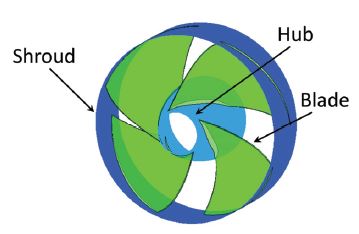
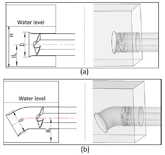
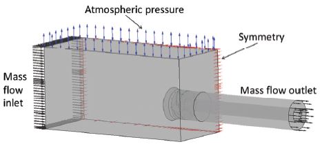
Fig. 1 and Table 1 show the 3D modeling and design parameters of an axial pump model. Fig. 2 and Table 2 show the gate pump-sump models and it’s design parameters, respectively. The width of gate pump-sump model is originally set by 2400mm with two sets of axial pump parallel installation but in this study, only one half of the flow field with one set of axal pump installation is adopted in consideration of computational time and machine capacity. Therefore, the symmetry boundary condition is set on the wall of one side wall and no-slip wall condition on the other walls of the pump sump model. The bell mouth inlet diameter and the pump center height from the pump-sump bottom are respectively set to D=600mm and Hc=535mm, equally to both of the gate pump types.
2.2 Numerical methods and boundary condition
The commercial CFD code of ANSYS CFX(8) has been employed to implement the CFD analysis of horizontal and elbow type gate pump-sump models. As a preliminary study for the 3D two phase flow field of the gate pump-sump, the effect of pump intake leaning angle and flow rate on the internal flow of the pump sump model was investigated for the validation and reliability of this CFD analysis method(9).
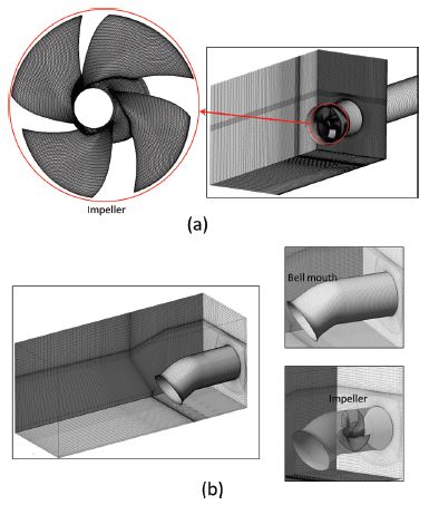
Numerical methods and boundary condition are shown in Table 3. The three dimensional fluid domain of the gate pump-sump models was constructed and the numerical grids of fine hexahedral mesh were applied for a better prediction of air and water flow characteristics in the gate pump-sump models as shown in Fig. 3.
The non-dimensional distance from the wall, y+, is a very important factor in numerical analysis to ensure the accuracy of the prediction results. Therefore, in this study, the y+ value of impeller, where is most complex blade shape and complicated flow field, was set below 10. A mesh number of 2.3 million was selected to implement the CFD analysis for both horizontal and elbow type gate pump-sump models. The two phase flow analysis(Air and water) was carried out. The multi-phase model of homogeneous has been applied in the numerical simulations. The general connection at the rotational interface and fixed interface was set as transient frozen rotor for a unsteady state calculation. The steady state calculation result was used as the initial condition to conduct the unsteady state calculation. The mass flow rates were applied at the inlet of the pump-sump and outlet of the gate pump models for CFD analysis, respectively.
Fig. 4 and Table 4 show the boundary condition of gate pump-sump model with axial pump model and simulation cases by pump type, water level and given flow rate at the gate pump-sump models, respectively. The water level of Case 1 was set to H=1200mm initially but the water level goes down gradually as calculation time goes on because the boundary condition of the outlet of the axial gate pump is set to design flow rate Q but the gate pump-sump inlet boundary condition is fixed to 2/3 times of the design flow rate. The other cases have the constant inlet and outlet flow rate condition and maintains constant water level.
According to the previous studies(1-6), the formation of various vortices are quite complicated at various water levels and flow rates.
The air entrainment should be deeply analyzed to improve the suction capacity of the pumping system. Therefore, the Case 1 is set at a relatively higher water level of horizontal gate pump model. From Cases 2 to 5, various water levels were set in the suction sump with constant flow rate at the inlet and outlet of horizontal gate pump model. At the lowest water level of H=900mm, the elbow gate pump model was added and analyzed to compare with the other cases.
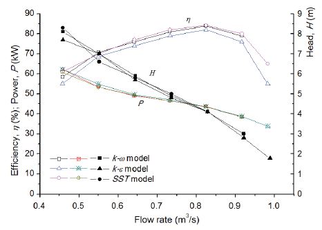
Moreover, in order to validate the influence of turbulence models, various turbulence models of k-ε, k-ω and SST were employed to conduct the turbulence model dependence test for the axial pump installed in the gate pump-sump models, which was illustrated in Fig. 5. The performance curves show similar tendency by the three various turbulence models. The axial pump model installed in the gate pump-sump model achieved a best efficiency of η=84% at the design flow rate of Q=0.83m3/s, at which the effective head is around 4m. Among the turbulence models, the shear stress transport(SST) turbulence model has been adopted in this study because of its relatively good convergence in the complicated flow field of turbo-machinery and advantages to estimate both separation and swirling flow on the complex flow field.
3. Results and discussion
3.1 Performance curves
To evaluate the overall performances of axial pump installed in the horizontal and elbow gate pump models, the efficiency of axial flow pump is defined by the equation as follows:
| (6) |
Where η is the pump efficiency; T is the input torque; ω is the angular velocity; ρ is the water density; g is the gravitational acceleration; Q is the flow rate and Hp is the effective head of the axial flow pump.
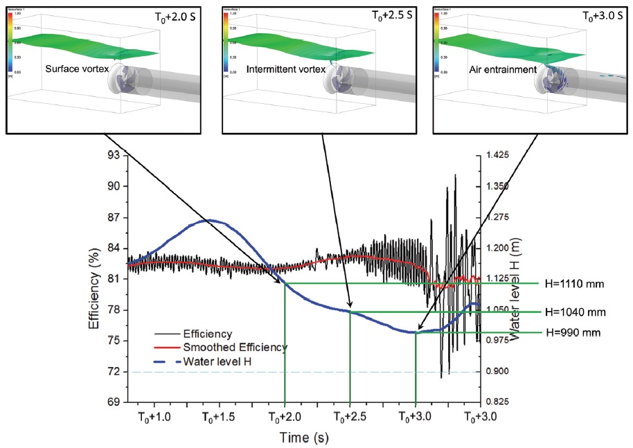
Fig. 6 presents the axial flow pump efficiency variation due to the change of the water level in the gate pump-sump model by Case 1. The ordinate of Fig. 6 indicates the axial pump efficiency and the water level, and the abscissa indicates the operating time.
Because the water flow rate at inlet is fixed to two thirds times of the discharge flow rate, the water level decreases by the operation time.
Finally, if the water level becomes close to the pump bell mouth upper tip, air with water inhales into the pump. Moreover, the water level oscillates a lot when the water level close to the pump inlet. Therefore, the pump performance is influenced drastically by the oscillation of water level as well as the air entrainment in the gate pump sump model. According to the calculated results, it can be observed that as the water level becomes down, the surface vortex and intermittent vortex occurred at the time of (T0+2.0)s and (T0+2.5)s, respectively. The efficiency of axial pump can be maintained steadily at first, but after the operating time goes by, the water level becomes close to the pump intake and much of the air from outside is inhaled into the suction pipe as illustrated at the time of (T0+3.0)s, and then the oscillation of axial pump efficiency became larger.
3.2 Air entrainment flow characteristics
Fig. 7 shows the flow pattern in the horizontal gate pump-sump model at the water level H=1110mm (Case 2). It can be clearly observed that the water surface in the gate pump-sump model maintains relatively steady and uniform flow field. There is no air entrainment into the bell mouth of the axial pump model.
Fig. 8 illustrates the flow behavior in the horizontal gate pump-sump model with axial flow pump at the water level of H=1040mm (Case 3). As seen from Fig. 4, it can be seen that at this water level the efficiency curve of axial pump became unstable and the intermittent vortex occurred. The occurrence of intermittent vortex means the air could be inhaled following the vortex core. The air entrainment could affect the hydraulic performance of axial pump.
Fig. 9 illustrates the flow behavior in the horizontal gate pump-sump model at the water level of H=990mm (Case 4). The surface vortex occurred from the operation start time of T0 and then much of air was inhaled into the gate pump at the time of (T0+1)s and (T0+2)s. The instability of axial pump increases a lot because of the suction of air, accordingly the efficiency oscillation of the axial pump increases.
Figs. 10 and 11 show the flow behavior in the horizontal and elbow gate pump-sump models at a the lowest water level of H=900mm, respectively. From the starting time of operation, the water level in the horizontal gate pump-sump model is quite unstable and much of air is inhaled into the pump suction bell mouth. With the increase of the operation time, more air is remarkably inhaled into the pump, and the mixing flow pattern of water and air in the horizontal gate pump-sump model is very complicated.
However, for the elbow gate pump-sump model, during the whole operation process, even though there is unstable water level fluctuation, there is no large amount of air suction into the elbow gate pump model. It can be inferred that the water level limitation should be paid attention and the suction bell mouth structure shape should be well designed for the application of gate pump. The elbow type gate pump model showed more advantages than the horizontal type gate pump.
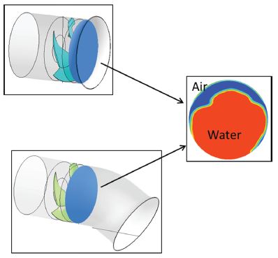
To investigate the flow rate of air entrainment into the horizontal and elbow gate pump models at the lowest water level of H=900mm, a measurement location of water and air volume fraction is fixed in front of the axial pump model as shown in Fig. 12. The volume fraction of water and air were calculated and compared by the variation of operation time.
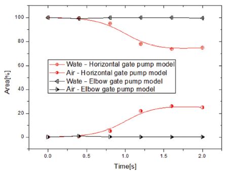
The comparison of water and air volume fraction at the fixed location of horizontal and elbow gate pump models is shown in Fig. 13. It can be found that the air is inhaled into the horizontal gate pump model from the starting time of operation and then the volume fraction of air gradually increases. After the operation time of (T0+1.5)s, the air volume fraction becomes more than 20% of the total discharge flow rate. However, there is almost no air entrainment into the elbow gate pump model and the air volume fraction keeps nearly 0 during the whole operation time. It is clear that the elbow gate pump is easier to control and suppress the air entrainment around the suction bell mouth than the horizontal gate pump.
4. Conclusions
The hydraulic performance and air entrainment flow behavior of axial pump installed in the two types of gate pump-sump models were evaluated by CFD analysis. 6 cases of the pump-sump water level and 2 types of gate pump inlet bell mouth shape were adopted to investigate the effect of water level and inlet bell mouth shape on the pump performance and pump-sump flow behavior. From the numerical simulation results, it is concluded that the water level showed a great effect on the hydraulic performance of the gate pump. The air is easier to be inhaled into the gate pump under the condition of a relatively low water level, and then eventually the instability of the gate pump performance will be increased, which is quite severe operation condition and the limitation of the low water level should be fixed to avoid the operation under the limit. Moreover, the elbow type gate pump could effectively reduce the air entrainment than horizontal type gate pump. Therefore, the water level limitation should be paid attention and the suction bell mouth structure shape should be well designed for the application of gate pump.
References
-
J. Matsui, Y. Sugino and K. Kawakita, "Numerical Simulation on Flow in Pump Sump with Free Surface," Proceeding of the 6th International Symposium on Fluid Machinery and Fluids Engineering, Wuhan, China, 2014.
[https://doi.org/10.1049/cp.2014.1249]

- T. Okamura, K. Kamemoto and J. Matsui, "CFD Prediction and Model Experiment on Suction Vortices in Pump Sump," The 9th Asian International Conference on Fluid Machinery, Jeju, Korea, 2007.
- T. Okamura, and K. Kamemoto, "CFD Simulation of Flow in Model Pump Sumps for Detection of Vortices," Proc. of 8th Asian International Fluid Machinery Conference, Yichang, China, 2005.
- V. P. Rajendaran, G. S. Constantinescu and V. C. Patel, "Experiment on Flow in a Model Water-Pump Intake Sump to Validate a Numerical Model," Proc. of FEDSM'98, ASME Fluids Engineering Division Summer Meeting, June21-25, Washington, DC, 1998.
- K. Onitsuka, H. Ohba, M. Munekata and H. Terachi, “Studies on the impeller and guide vane of axial flow pump and shape of suction pipe for pump gate”, Proc. of 8th International Symposium on Experimental and Computational Aerothermodynamics of Internal Flows, Lyon, 2007.
-
F. Yang, C. Liu, “Numerical and experimental investigations of vortex flow and vortex suppression schemes in the intake passage of pumping system”, Advance in Mechanical Engineering, Article ID: 547086, 2014.
[https://doi.org/10.1155/2014/547086]

-
J.-W. Choi, Y.-D. Choi, C.-G. Kim and Y.-H. Lee, “Flow uniformity in a multi-intake pump sump model”, Journal of Mechanical Science and Technology, vol. 24, No. 7, pp. 1389-1400, 2010
[https://doi.org/10.1007/s12206-010-0413-5]

- ANSYS Inc, ANSYS CFX Documentation Ver. 18.1 http://www.ansys.com, (2019)
- Y. Lee, K.-Y Kim, Z. Chen and Y.-D. Choi, “The Effect of Pump Intake Leaning Angle and Flow Rate on the Internal Flow of Pump Sump”, The KSFM Journal of Fluid Machinery, vol. 39, No.8, pp.849-855, 2015.
