
Influence of Leakage Flow through the Labyrinth Seal Gap on the Hydraulic Performance of a High-Head Two-Stage Centrifugal Pump
Abstract
Two-stage centrifugal pumps are designed for high-head applications, which require higher pressure generation by the pump. The labyrinth seal is the primary mechanism for controlling the contact between rotating parts and stationary parts in a pump. A small, non-contacting radial clearance gap is maintained to allow for the rotary motion. Hence, leakage flow occurs through the labyrinth seal clearance gap, returning to a low-pressure region in the system. Numerical analysis is performed to evaluate the performance and internal flow variation of the labyrinth seal gap under varying flow conditions. The analysis shows efficiency reduction with an increase in the labyrinth seal gaps of 0.5 mm, 1 mm, and 2 mm.
Keywords:
Centrifugal pump, High-head two stage, Labyrinth seal gap, Leakage flow, Performance키워드:
원심펌프, 고양정 2단, 리비린스 씰 간극, 누설흐름, 성능1. Introduction
The fundamental design of a multi-stage centrifugal pump involves the arrangement of multiple impellers in series, typically mounted on a common shaft(1). This configuration achieves a proportionally higher delivery head than that of a single-stage pump(2). The total head generated by the pump is the cumulative sum of the head produced by each stage(3). By its nature a high-head pump is a high-pressure differential machine. In a two-stage pump configuration, the fluid at the outlet of the second-stage impeller at a significantly elevated pressure. This high pressure zone is in proximity to the pump's initial low-pressure suction zone at the inlet of the first stage and has an unavoidable connection through the labyrinth seal gap(4). The inter-stage leakage path is an internal seal that must be placed in order to maintain the rotating shaft within the stationary casing. Consequently, the design inherently creates a massive pressure gradient across this inter-stage seal(5). This pressure difference is the fundamental driving force of the leakage flow, which is subjected to the analysis(6). For the internal sealing in high-performance turbomachinery, labyrinth seals are a preferred solution(7).
The labyrinth seal does not eliminate leakage but controls and minimizes it by creating a tortuous path for the fluid(8). This path is composed of a series of sharp, throttling teeth and expansion cavities(9).This geometry forces the fluid to navigate a complex path, creating areas of high turbulence and dissipating the fluid's kinetic energy, thereby restricting the flow for a given pressure difference(10). High-head pumps, in order to generate the design head, are often operated at high- pressure conditions. In these high-pressure rotating devices, any form of contact seal would generate catastrophic levels of frictional heat and wear, leading to rapid failure(11). A non-contacting seal is therefore a mechanical necessity to avoid these failures(12). Inherent to its construction, a non-contacting labyrinth seal must maintain a small radial clearance gap to avoid contact between the rotating and stationary components.
The purpose of this study is to investigate the effect of flow leakage through the labyrinth seal gap on the hydraulic performance of a two-stage centrifugal pump.
2. 3D Modeling of Pump
2.1 Geometric model of two-stage centrifugal pump
The 3D model of the two-stage vertical centrifugal pump was developed based on the design specifications presented in Table 1. With a specific speed of 125 (min⁻¹, m³/min, m), the pump falls within the category of low-specific-speed pumps, making it suitable for high-head, low-flow applications.

Design specifications of the pump
The two-stage pump in this study consists of an inter-stage type labyrinth seal installed adjacent to the rotor shaft, between the two stages, to reduce the leakage flow from recirculating from the 2nd stage impeller hub region to the 1st stage impeller hub. A staggered type labyrinth seal is used in the pump design. Fig. 1 and Table 2 show the detailed geometry and dimensions of the labyrinth seal, including the two stages of impellers. Diffuser chambers within the inter-stage labyrinth seal are numbered sequentially from 1 to 11, starting from the 2nd stage impeller hub and progressing toward the 1st stage impeller hub as shown in Fig. 1. Case 0 is a hypothetical case in which labyrinth seal was not considered. In other cases constant value of b₂ were maintained. In Case 1 and Case 2 t₁ was increased by 0.5 mm and b₁ by 0.25 mm, while in Case 3 t₁ was increased by 1 mm and b₁ by 0.5 mm, as shown in Fig. 2 and Table 2. These values were selected in accordance with the API 610 standards for metallic wear rings(13).
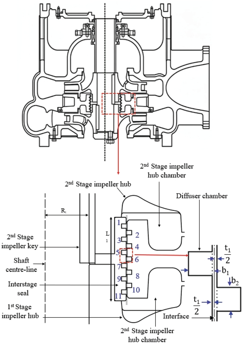
Cross sectional view of the inter-stage labyrinth seal
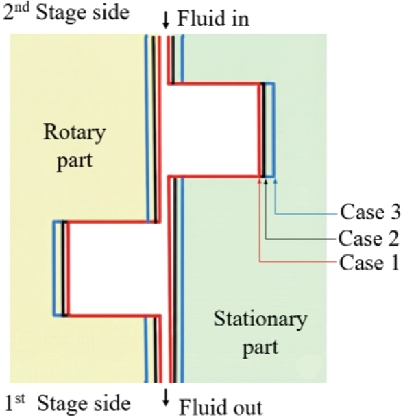
Design cases for the labyrinth seal
Parameters of the inter-stage labyrinth seal
3. Numerical methodology
3.1 Numerical model
Numerical grids were created for the fluid domain of the two-stage centrifugal pump shown in Fig. 3 and Fig. 4. The crossover directs the flow from the 1st stage impeller to the 2nd stage impeller. A grid dependency study was conducted for the mainstream under the hypothetical condition with no leakage gap. When the grid number reached 3.55 million, the grids of the pump's overall efficiency and head were found to be independent of the grid size, as shown in Fig. 5. The numerical grid for the leakage path was generated such that the y+ value is less than 2, with a 1st layer thickness of 0.02 mm to capture the boundary details near the leakage path walls. Consequently, by combining this with the mainstream path mesh total grid count of 4.33, 4.41, and 4.64 million grids, were selected for the whole computational fluid domain for Case 1, Case 2, and Case 3, respectively.
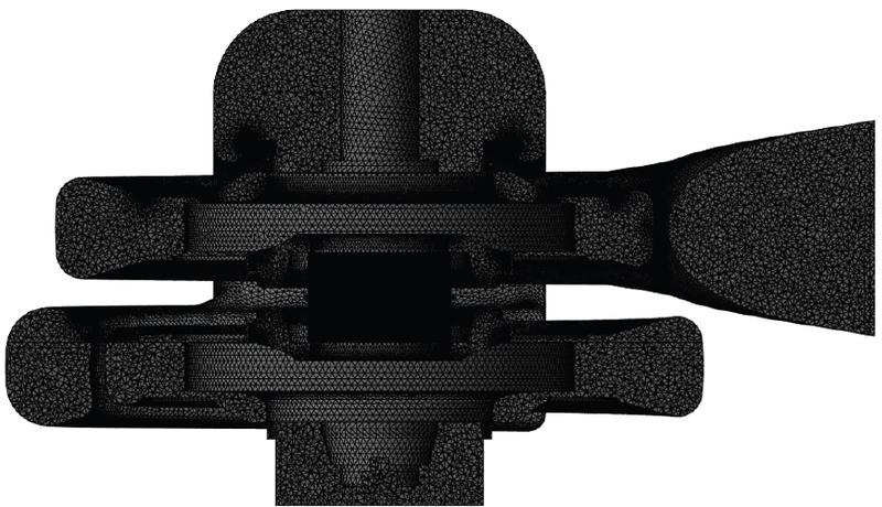
Cross sectional view of the numerical grid for the pump fluid domain
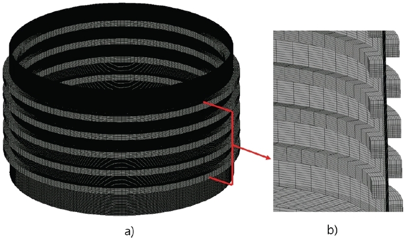
Numerical grids of the leakage path for case 2 a) 3D and view b) Cross sectional view
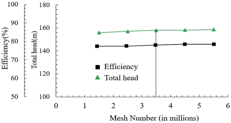
Mesh independence test
For the CFD analysis, conditions shown in Table 3 were used in the ANSYS CFX(14) setup. Due to the non-contacting nature of the labyrinth seal, an isothermal condition was used in the analysis. First, the simulation was carried out to validate the realistic nature of the numerical model, and Fig. 6 shows the typical centrifugal pump characteristics for total head, input power, and hydraulic efficiency. In this study, this was considered Case 0, where there is no inter-stage labyrinth leakage path in the design. To evaluate the effect of leakage flow on the pump's hydraulic performance, steady-state CFD calculations were performed at different flow rates for different labyrinth seal gap cases.
Boundary conditions of the CFD analysis
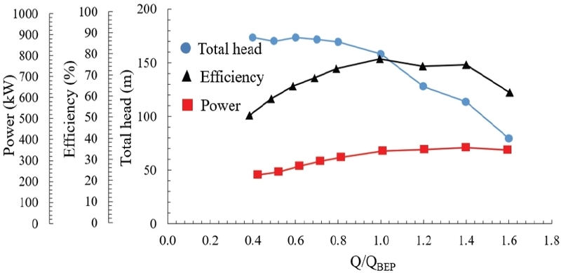
Performance curves of the two-stage centrifugal pump
4. Results and Discussion
4.1 Leakage flow analysis
Due to the staggered-type labyrinth seal, a cavity leakage flow was observed within the labyrinth seal gap. Fig. 7 shows the flow pattern in the 4th diffuser chamber. Fluid flowing through the gap t₁ has a comparatively higher velocity and exhibits laminar flow behavior, while the fluid which is inside the leakage gap shows internal circulatory flow. This is illustrated in the Fig. 7. The static pressure variation at the partial flow condition (Q/QBEP=0.8), design flow rate (Q/QBEP=1.0), and excessive flow rate condition (Q/QBEP=1.2) from the 3rd diffuser chamber to the 8th diffuser chamber is shown in Fig. 8. Moving from the 3rd chamber to the 8th chamber, the results show a gradual pressure drop as the flow moves from the high-pressure side to the low-pressure side. As the flow rate increased, the pressure in each labyrinth fluid gap section was observed to reduce. In order to investigate the intensity of flow-circulation variation with the change in flow rate, vorticity defined by Eq. (1) in the yz plane was computed using the numerical results.
| (1) |
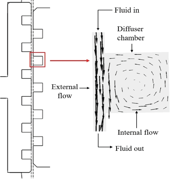
Labyrinth gap flow pattern nomenclature
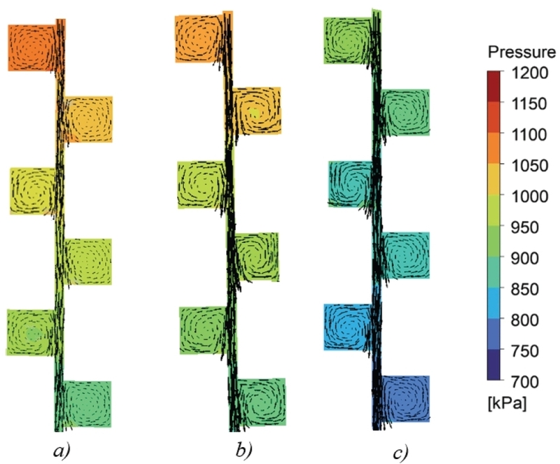
Vector plots and pressure contours of diffuser chambers 3 to 8 for Case 1 at a) Q/QBEP=0.8, b) Q/QBEP=1.0, and c) Q/QBEP=1.2
where ωx is the vorticity about x axis which represent the tendency of a fluid to rotate about x axis in the flow field of U=u(v, w) in plane yz.
Fig. 9 represents the ωx variation with the normalized distance measured along the blue line from point A to point B in line with the leakage flow direction from the 3rd diffuser chamber to the 8th diffuser chamber. The results show a similar pattern with an increase of flow rate. The circulation in the diffuser chambers closer to the rotor shows negative values of vorticity, while the chambers opposite to them show positive values. This indicates that the circulation in the adjacent chambers is in opposite directions to each other. Further, increases of 9.3% and 6.7% in the magnitude of vorticity (measured about the x-axis) were observed when changing from the flow rate condition of Q/QBEP=1.2 to Q/QBEP=1.0 and from Q/QBEP=1.0 to Q/QBEP=0.8, respectively.
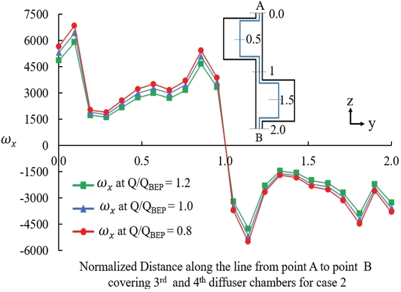
ωx along the line from point A to point B, covering the 3rd and 4th diffuser chambers for Case 2 at Q/QBEP=0.8, Q/QBEP=1.0, and Q/QBEP=1.2
Fig. 10 shows the surface vectors and the pressure variation across the labyrinth gap for the three cases in this study. As the labyrinth gap increases, the pressure tends to decrease in the labyrinth gap fluid from Case 1 to Case 3. Furthermore, due to the widening of the leakage gap, more leakage fluid will pass through as external flow, which is indicated by a higher number of vectors in the gap t1. Fig. 11 shows the mass leakage flow rate ratio through the labyrinth seal gap where is the mass flow rate through the labyrinth seal gap and is the mass flow rate into the pump in kg/s. The mass flow rate increases from Case 1 to Case 3. The operating condition also affects the flow rate through the labyrinth gap. As the pump flow rate increases, the leakage flow decreases. As the flow condition changes for Case 1 from Q/QBEP =0.8 to Q/QBEP=1.0, the mass flow rate ratio decreases by 1% and also when it changes from Q/QBEP=1.0 to Q/QBEP=1.2, the mass flow rate ratio decreases by another 1%. However, this linearity exists only after the flow condition of Q/QBEP =1.0.
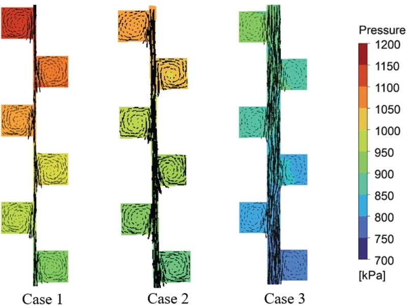
Vector plots and pressure contours of diffuser chambers 3 to 8 for Case 1, Case 2, and Case 3 at Q/QBEP=1.0.
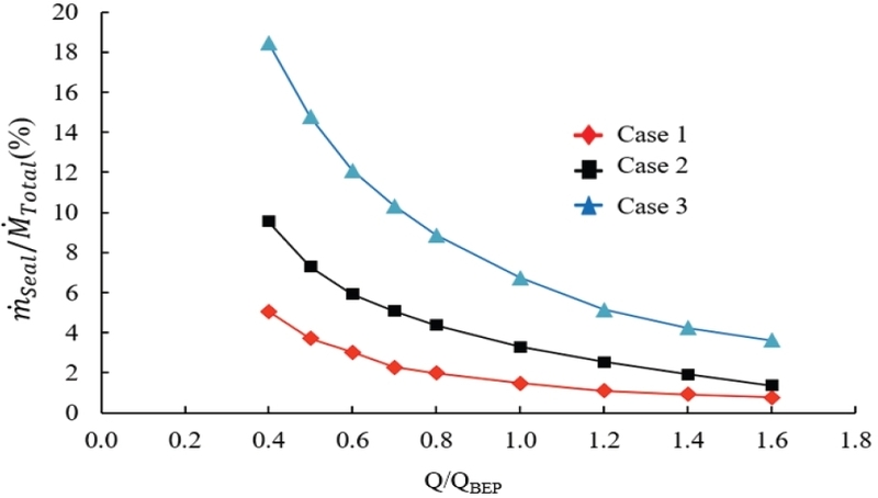
Mass leakage flow rate ratio variation with the flow condition for the Case 1, Case 2 and, Case 3
4.2 Effect of leakage flow on the main flow
The fluid compartments separating the 1st stage hub and leakage path for Case 0 and Case 2 are shown in Fig. 12 a) and b), respectively. An imaginary leakage flow path is created for Case 0 to compare with Case 2. Due to the leakage flow, the pressure in the 2nd stage hub chamber is comparatively lower in Case 2 than in Case 0. Furthermore, as the temperature is uniform in the analysis, kinetic energy loss due to the circulating flow inside the labyrinth seal diffuser chamber leads to a reduction in fluid pressure. This phenomenon ultimately affects the change in overall hydraulic efficiency of the pump.
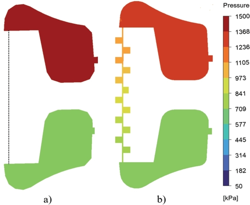
Pressure contours for 1st stage and 2nd stage impeller hub chamber for the a) Case 0 and b) Case 2 at Q/QBEP=1.0.
Fig. 13 shows the pump hydraulic efficiency variation for Case 0, Case 1, Case 2, and Case 3 at different flow rate conditions. The variation in efficiency is similar across all three labyrinth seal gap conditions. However, there is a tendency to drop the efficiency as the labyrinth leakage gap increases from Case 0 to Case 3. Case 3 exhibits the highest drop of 4% efficiency at the best efficiency point operation compared to Case 0.
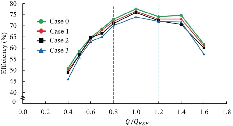
Pump efficiency variation comparison for the Case 0, Case 1, Case 2, and Case 3
5. Conclusion
The influence of the inter-stage labyrinth seal gap on the performance of a two-stage centrifugal pump was examined using a numerical approach. Three design cases were analyzed to investigate how the changes in labyrinth seal gap affect internal flow variations within the fluid regions.
According to the analysis, it was concluded that as the fluid flow rate to the pump increases, the pressure inside the labyrinth seal gap tends to decrease. Due to this pressure reduction, the leakage mass flow rate through the labyrinth seal decreases. The reduction in the leakage flow is not linear with the increase in the flow rate into the pump. At partial flow rate conditions, the rate of change in leakage flow is higher than that at the excessive flow rate conditions. However, as the labyrinth seal clearance increases, pressure tends to decrease, but this is accompanied by a larger leakage flow due to the larger clearance gap. Due to this change in the design of the labyrinth gap, the hydraulic efficiency tends to be reduced compared to the hypothetical case 0 in the study. However, the efficiency drop is in the range of 1%–5% for all the design cases at all the flow rate conditions, while a 5% drop is observed only in design case 3 at the flow rate condition of Q/QBEP = 0.4. Considering the analysis, Case 1 can be suggested as the optimal configuration. Adopting Case 1 yields an efficiency gain of up to 3% compared to Case 2 for the operation range from Q/QBEP =0.8 to Q/QBEP =1.2. Comparing Case 1 with Case 3 at the Q/QBEP =1.0 flow condition, where the pump operates most frequently, there is an efficiency drop of 3%. Furthermore, Case 1 provides a compelling balance between regulatory API 610 standards and pump efficiency. However, an optimal design with cost consideration will be done in future analysis to evaluate the optimal labyrinth seal gap.
Acknowledgments
This research was supported by the ANCHOR program through the Jeollanamdo ANCHOR center, funded by the Ministry of Education(MOE) and the Jeonnam-Gwangju Special Metropolitan City, Republic of Korea(2026-ANCHOR-14-001).
References
-
L. Kerbouci and G. Dituba Ngoma, 2015, “Parametric Study of Liquid Flow in Five- and Six-stage Centrifugal Pumps,” Proceedings of the 5th International Conference on Simulation and Modeling Methodologies, Technologies and Applications, pp. 178∼182.
[https://doi.org/10.5220/0005543601780182]

-
N. La Roche-Carrier, G. Dituba Ngoma, and W. Ghie, 2014, “Numerical Investigation of Liquid Flow in Two-, Three- and Four-Stage Centrifugal Pumps,” Proceedings of the 4th International Conference on Simulation and Modeling Methodologies, Technologies and Applications, pp. 92∼99.
[https://doi.org/10.5220/0005096800920099]
-
M. M. Shamsuddeen et al., 2021, “Flow Field Analysis and Feasibility Study of a Multistage Centrifugal Pump Designed for Low-Viscous Fluids,” Applied Sciences, Vol. 11, No. 3, p. 1314.
[https://doi.org/10.3390/app11031314]
-
T.-W. Ha, Y.-B. Lee, and C.-H. Kim, 2002, “Leakage and rotordynamic analysis of a high pressure floating ring seal in the turbo pump unit of a liquid rocket engine,” Tribology International, Vol. 35, No. 3, pp. 153∼161.
[https://doi.org/10.1016/S0301-679X(01)00110-4]
-
A. Patil, M. Kasprzyk, A. Delgado, and G. Morrison, 2020, “Effect of Leakage Flow Path Wear on Axial Thrust in Downhole Electrical Submersible Pump Unit,” Journal of Fluids Engineering, Vol. 142, No. 5.
[https://doi.org/10.1115/1.4045571]
-
G. Zhao, J. Xu, J. Lian, Y. Lin, and Z. Zhu, 2025, “Research on the Impact of Labyrinth Seal Ring Tooth Profile on the Pressure Pulsation of Leakage Chambers in High-Speed Centrifugal Pumps,” Lubricants, Vol. 13, No. 7, p. 308.
[https://doi.org/10.3390/lubricants13070308]
-
D. W. Childs and J. K. Scharrer, 1986, “Experimental Rotordynamic Coefficient Results for Teeth-on-Rotor and Teeth-on-Stator Labyrinth Gas Seals,” Journal of Engineering for Gas Turbines and Power, Vol. 108, No. 4, pp. 599∼604.
[https://doi.org/10.1115/1.3239953]
- Bijay Sultanian, 2018, “Labyrinth Seals,” Cambridge University Press eBooks, pp. 237∼257.
-
G. Vermes, 1961, “A Fluid Mechanics Approach to the Labyrinth Seal Leakage Problem,” Journal of Engineering for Power, Vol. 83, No. 2, pp. 161∼169.
[https://doi.org/10.1115/1.3673158]
-
R. Corral, M. Greco, and A. Vega, 2021, “Effective Clearance and Differential Gapping Impact on Seal Flutter Modeling and Validation,” Journal of Turbomachinery, Vol. 144, No. 7.
[https://doi.org/10.1115/1.4053290]
-
B. Vijayaragavan, S. P. Asok, and M. K. Marichelvam, 2025, “Optimizing the labyrinth geometric parameters and modeling a new twin seal configuration for improved sealing efficiency in gas turbines,” Frontiers in Mechanical Engineering, Vol. 11.
[https://doi.org/10.3389/fmech.2025.1440903]
-
Y. Wang et al., 2025, “Development Status of Dynamic Sealing Technology and Discussion on Advanced Sealing Technologies,” Lubricants, Vol. 13, No. 1, p. 11.
[https://doi.org/10.3390/lubricants13010011]
- Centrifugal Pumps for Petroleum, Petrochemical, and Natural Gas Industries, API Standard 610, 12th ed., American Petroleum Institute, Washington, DC, USA, 2021.
- ANSYS Inc., 2025, “ANSYS documentation ver 2025R1”, http://www.ansys.com, .