Initial Hydraulic Design and Performance Analysis of 300 MW-Class Pump-turbine Model
Abstract
In Korea, the performance of some pumped storage plants, which were constructed in 1980s, is unsatisfactory after long periods of operation. Redesign of the pump-turbine impeller for these plants has become necessary. Currently, the design technology of pump-turbine is monopolized by foreign companies and there’s lack of development of independent design ability in Korea. This study is an attempt to design a pump-turbine impeller that will contribute to the development of pump-turbines in Korea. The study has focused on two types of hydraulic designs. However, these are not complete designs so many assumptions have been made to complete the design process. Some important factors have been highlighted for an initial design. Additionally, actual dimensions of the pump-turbines are not publicly available. Therefore, by using a head of 350 m and flow rate of 100 m3/s from 300 MW-class pump-turbines, the impeller design was investigated. The first design is by selection of discharge speed constant from centrifugal pump design and the second design is by selection of gradient of discharge variation to head variation. From this study it was found that the second design method is most suitable for obtaining a good initial design.
Keywords:
Pump-turbine, Hydraulic Design, Impeller, Performance, Internal Flow키워드:
펌프터빈, 수력설계, 임펠러, 성능, 내부유동1. Introduction
In developed countries with expanding economies, there is increasing demand for energy that calls for new and efficient power plants. Pumped storage plants are one of the most reliable systems for equalizing the power supply and demand. It provides balancing power for grid stability and can provide fast response within seconds to regulate the electrical grid during periods of rapidly changing demand.(1)
The Yangyang Pumped Storage Power Station uses the Namdae-Chun River to operate a 1,000 MW pumped storage hydroelectric power system, about 10 km west of Yangyang in Gangwon Province, Korea. Construction on the power plant began in 1996 and it was completed and dedicated on September 13, 2006. The power plant contains four 250 MW reversible Francis turbine generators for an installed capacity of 1,000 MW.(2) Table 1 shows the finished construction pumped storage plants in Korea. The capacity range of the plant is between 400 to 1000 MW.
In Korea, the performance of some pumped storage plant, which were constructed in 1980s, is unsatisfactory after long periods of operation. Redesign of the pump-turbine impeller for these plants have become necessary. Currently, the design technology of pumpturbine is monopolized by foreign companies and there’s lack of development of independent design ability in Korea. This study is an attempt to design a pump-turbine impeller that will contribute to the development of pump-turbines in Korea. There are two methods discussed in this paper. Each method has an important factor that affects the overall performance of the pump-turbine. These factors have been highlighted in this study.
2. Pump-turbine Impeller Design
The study has focused on two types of hydraulic designs. However, these are not complete designs so there are many assumptions that have been made to complete the design process. Additionally, actual dimensions of the pump-turbines are not publicly available. Therefore, by using a head of HP=350 m and flow rate of Q=100 m3/s from P=300 MW-class pumpturbines, the impeller design was investigated. The turbine mode design head is HT=340 m and flow rate is Q=115 m3/s. The corresponding specific speeds for pump and turbine modes are nsp=37 m-m3/s and nst=110 m-kW respectively. The first design considers the discharge speed constant derived by Stepanoff’s centrifugal pump design(3) and the second design considers the gradient of discharge variation to head variation derived from pump-turbine design by Kubota.(4)
Most modern pump-turbines are developed using the pump design method. However, the design procedure does not completely follow the pump design method and is modified to accommodate the turbine mode. The blade number is reduced and blade length is increased. The blade exit width is also increased to cater for the added guide and stay vanes. For the past century, developed countries like America, Europe and Japan have devised pump-turbine designs by conducting several experiments and developed their own theories and relevant factors important to the pump-turbine design.(4-7) It is used as a reference and certain techniques can be applied to the pump-turbine impeller design for the current study. The rotational speed is one of the most important parameters that are selected first. Most large pump-turbines greater than P=300 MW-class capacity have a rotational speed of n=300 min-1.(1,5) This study will also use this rotational speed. Both of the pump and turbine modes are operated at the same rotational speed because a synchronous motor generator is utilized in modern pump-turbines.
2.1 Pump Design by Discharge Speed Constant ‘Ku’
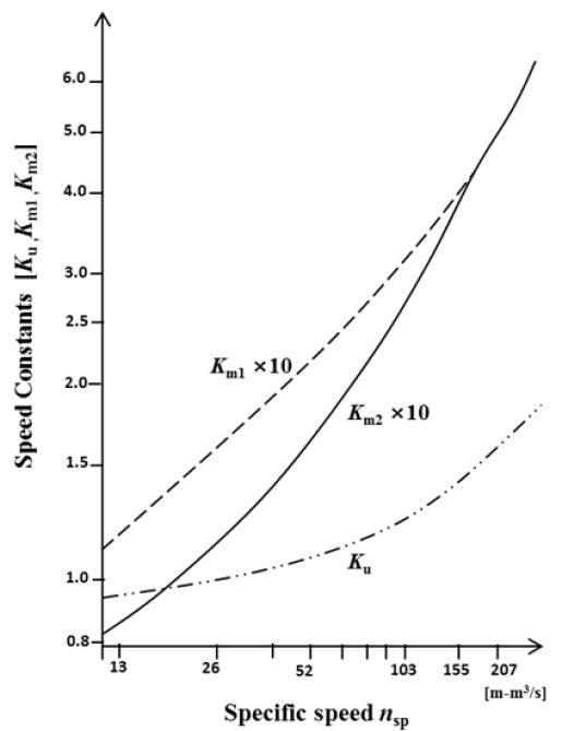
By referring to the basic hydraulic design of centrifugal pump, some initial dimensions for the meridional shape can be developed.(3) The following method is adapted from reference (3). There is a relationship between the pump and turbine specific speeds. The turbine specific speed is approximately three times the pump specific speed. Using the specific speed, several important speed constants and inlet to outlet diameter ratios can be determined for the initial design. However, it should be noted that the pumpturbine needs a larger impeller exit width, which cannot be accurately determined from Fig. 1 and several trials have to be conducted to find near design point. The purpose of studying this method is to determine the correct impeller exit width Bg for a pump-turbine system by using the existing pump design method.
The specific speed of the pump and turbine can be calculated by equations (1) and (2) respectively:
| (1) |
| (2) |
Another important factor in the design is the speed constant that gives the relation between the pump total head and the impeller peripheral velocity. Fig. 1 displays the relationship of several impeller constants to the specific speed. The most widely used speed constant Ku is defined in equation (3):
| (3) |
Where u2 is the peripheral velocity at impeller exit. From Fig. 1, the values for Ku and Km2 (speed constant at exit of meridional line) were estimated as 1.04 and 13.5 respectively. Equations (4) and (6) were utilized to calculate the initial impeller dimensions:
| (4) |
Where ω is the angular velocity. From equation (4) the impeller blade diameter, D2 is calculated.
| (5) |
Using the speed constant Km2, the meridional velocity, cm1P is obtained from equation (5). Using the meridional velocity the Bg is calculated by equation (6):
| (6) |
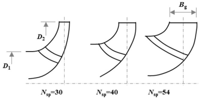
The value of Bg obtained from here is too small and cannot be used for the pump-turbine so it needs to be modified because of the addition of guide vanes and stay vanes. Other meridional shapes for pumpturbines at the design specific speed were also referred to estimate the initial meridional shape as shown in Fig. 2.(6,7) It was noted from comparing other pumpturbine meridional shapes that a pump-turbine of similar size has almost twice the Bg of a normal centrifugal pump. Thereby, the calculated Bg was increased by a factor of 2.00, 2.03, 2.13 and 2.19 for further investigation. The initial design parameters are presented in Table 2, where four cases of blade exit width also known as guide vane height were investigated.
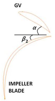
The impeller vane discharge angle β2 is one of the most important single design elements. An average value of 22.5° is commonly used for all specific speeds. The upper limit of β2 may be raised to 27.5° without affecting the efficiency appreciably. The lower limit of β2 consistent with good design is about 17.5°.(3) Fig. 3 shows the blade angles at the impeller blade and guide vane. The guide vane angle α is assumed to be 25° for the initial design and using the velocity triangle the β2 can be calculated for both pump and turbine mode and checked with the range explained earlier. The initial β2 is calculated as 21.7° using the pump flow rate and 26.9° using the turbine flow rate. The values are within the range of normal centrifugal pump designs. The blade angles has been kept constant for both design methods.
2.2 Pump-turbine Design by Gradient of Discharge Variation to Head Variation ‘gQ/H’
A fundamental procedure for hydraulic design of major dimensions of a Francis pump-turbine can be obtained from the method described by T. Kubota.(4) However, detailed designs on the blade loadings are not discussed. For this method, dimensions are obtained through the relationship of several constants to the specific speed of the pump mode. The method is suitable for nsp=30~60 m-m3/s and corresponding heads of 50~500 m.
Using the specific speed of the pump the corresponding constants can be obtained from Fig. 4 and estimation of the impeller meridional shape can be obtained from equations (7) to (10). The gradient of discharge variation to head variation gQ/H is the most important factor that affects the overall size of the pump-turbine. The purpose of studying this method is to determine an appropriate factor of the gradient of discharge variation to the head variation gQ/H.
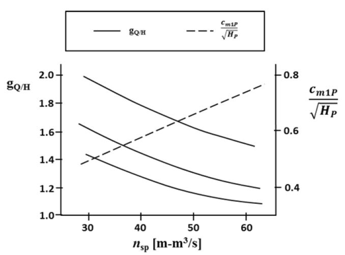
Gradient of discharge variation to head variation of pumping performance versus specific speed; meridional velocity at the impeller exit of a Francis pump-turbine(4)
The peripheral speed u2 at the impeller exit at best efficiency point can be expressed by the following equation:
| (7) |
From Fig. 4, three possibilities of gQ/H (1.8, 1.5 and 1.3) can be selected at nsp=37 m-m3/s from the three curves shown. After obtaining the peripheral speed the diameter at the impeller exit, D2 can then be found by equation (8), which also gives three possibilities of D2:
| (8) |
For the purpose of a rough estimation, the relation of cm1P/HP0.5 versus nsp is shown in Fig. 4. From this, the width Bg can be found by the following equation:
| (9) |
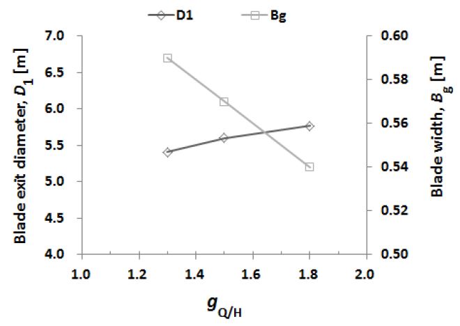
From equation (9) we get three values for width according to the three diameters calculated earlier Bg as 0.54, 0.57 and 0.59 m. Finally, a rough estimation of the impeller entrance diameter D1 can be determined by:
| (10) |
The initial design parameters are presented in Table 2, where three possible cases for initial design are presented as PT-D5765, PT-D5600 and PT-D5410. Considering the minimum and maximum size of the pump-turbine, two cases are conducted in this study to see which one performs best near the design condition. PT-D5765 and PT-D5410 are selected for further analysis. It is assumed that PT-D5600 would perform in between the two ranges.
3. Numerical Method
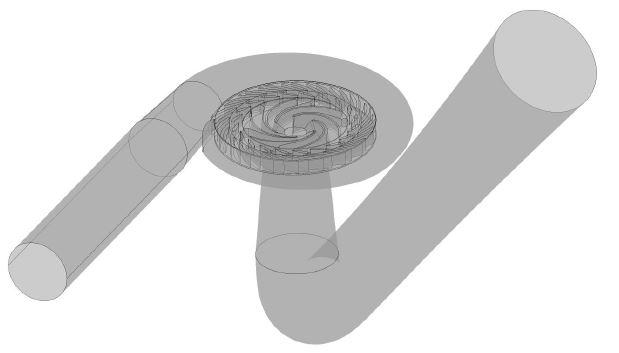
The fluid domain of the pump-turbine geometry was modelled in 3D and numerical mesh was generated. The analysis calculation was conducted using a commercial software ANSYS CFX.(8) Previously available shape for guide vanes, stay vanes, draft tube and casing for a Francis pump-turbine was used for the full domain analysis. It consists of spiral casing, 20 stay vanes, 20 guide vanes and impeller with 6 blades.(9-11)
The general connection between the rotational interface and fixed interfaces was set as frozen rotor for a steady state calculation. The shear stress transport turbulence model has been adopted in this study because of its superiority to estimate both separation and vortex occurrence on the wall of complex blade shapes. The total pressure boundary condition was applied at the inlet and static pressure was set for the outlet in the turbine mode (TM). With this boundary condition the head can be fixed while the flow rate is determined by calculation according to guide vane opening. For the pump mode (PM) the static pressure boundary condition was applied at the inlet and mass flow rate was set for the outlet. The boundary conditions for the numerical analysis are summarized in Table 3.
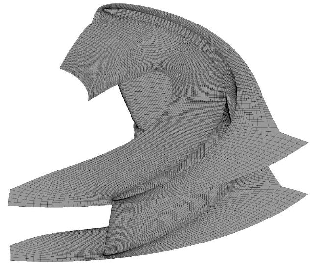
The numerical mesh for all components except the casing was constructed using hexahedral mesh. The casings complex geometry makes it difficult to generate hexahedral meshing in a short period of time, therefore tetrahedral meshing has been adopted only for the spiral casing. The full domain calculation model is shown in Fig. 5 and refined hexahedral mesh on a single impeller is shown in Fig. 6.
4. Results and Discussion
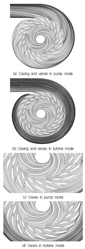
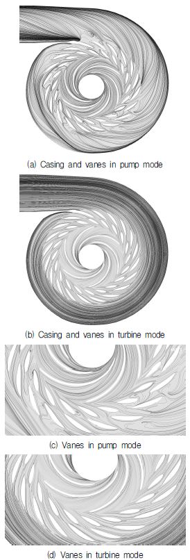
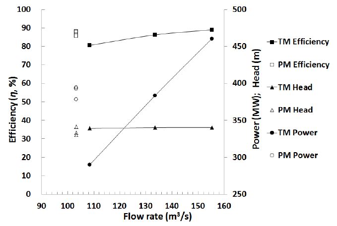
The results include the characteristics of flow rate, head, power and hydraulic efficiency to give an estimated performance of the pump-turbine. Fig. 7 and 8 compares the streamlines in cross-sections of the casing, stay vanes and guide vanes for the best results of the two methods: the first method by discharge speed constant Ku and the second method by gradient of discharge variation to head variation gQ/H. It can be observed that in the pump mode for both methods, recirculation flows continuously occur starting from the guide vanes. This is a common characteristic in pump mode because of the inclusion of vanes. However, the turbine mode for both methods show very smooth streamlines evenly distributed along the casing, stay vanes and guide vanes. The performance results for the two methods will be compared to the design conditions at best efficiency point. The design conditions are shown in Table 4.
4.1 Performance Characteristics by ‘Ku’
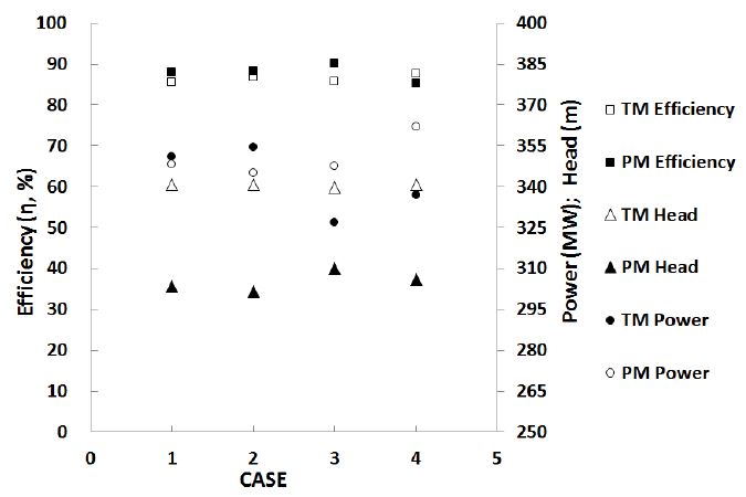
The first method by discharge speed constant Ku, produced four initial designs with different Bg dimensions. Among the four designs it can be seen that Case 3 with Bg of 0.68 m showed the best performance in the pump and turbine modes considering the nearest comparison to the design conditions. The results indicate that the design head was not achieved in pump mode for all the cases. This could be because of large recirculation flows in the guide vanes, stay vanes and casing as seen in Fig. 7, which would increase losses in these components. Another reason for a lower head could be due to the friction losses in the pipe. The turbine mode in contrast to pump mode shows relatively good comparison to the design conditions, but the efficiency is relatively lower. A summary of the results are shown in Fig. 9 and Table 5.
4.2 Performance Characteristics by ‘gQ/H’
Table 6 and Fig. 10 summarizes the performance characteristics by the different cases of gQ/H. This method by Kubota was studied in more detail in contrast to the previous method (Stepanoff) because it showed good comparison to the design conditions. Among the two designs PT-D5410 and PT-D5765 where gQ/H=1.3 and 1.8 respectively, it was observed that PT-D5765 showed a better performance in comparison to the design conditions at full guide vane opening. Therefore, PT-D5765 was investigated for other guide vane openings and it was found that the pump mode produced better performance at a smaller guide vane opening in contrast to the turbine mode.
4.3 Relationship of Bg and gQ/H
From the study it can be deduced that a higher value of gQ/H gives considerably better results on performance. Another factor that is affected by the selection of gQ/H is the Bg. The relationship of gradient of discharge variation to head variation gQ/H, blade width Bg and diameter D1 is plotted in Fig. 11. The gQ/H and Bg are inversely proportional to each other. A higher selection of gQ/H will result in a smaller Bg, where as a lower selection will result in a larger Bg. Additionally, it was observed that a lower gQ/H results in a smaller head in pump mode and a lower efficiency in turbine mode.
Comparing the size of Bg from the two methods, a large difference is observed. Initially, by the first method an increasing factor was applied on the calculated Bg size. However, this factor seems to be not well selected when comparing it to the second method. The best performance by the method of Ku shows that a Bg of 0.68 m is better, whereas the best performance from the method of gQ/H was found at a much lower Bg. This could mean that the size of Bg has a significant effect on the performance of the pump-turbine. However, the impeller diameters for the two methods do not show very large difference as seen in Table 2.
Moreover, the current methods discussed in this study is only for obtaining the initial design of the impeller blade. To improve the overall performance, the design of guide vane, stay vane and casing shapes must also be improved. However, the latter is not part of the scope of this study.
5. Conclusion
The study has presented two techniques in designing a pump-turbine system from provided information of head, flow rate and rotational speed. Comparing the two methods of discharge speed constant Ku, and gradient of discharge variation to head variation gQ/H, the second method of gQ/H is a good suggestion for initial design dimensions of the pump-turbine impeller blade. From the study of Bg it can be concluded that it gives significant effect to the overall performance. Additionally, the first method of Ku did not show much improvement to the efficiency in turbine mode. However, the study of gQ/H presented improved results in efficiency for both modes and also significant improvement of the head in pump mode. The inversely proportional relationship of gQ/H and Bg was also observed from the second method of gQ/H, which is an important contribution providing a better understanding to the designer when selecting a range for the size of the impeller blade. For future studies, further optimizations and much deeper study of the impeller blade loading and improvement to other componentssuch as guide vanes, stay vanes and casing-can see additional improvement in efficiency of both modes.
Acknowledgments
This work was supported by the New and Renewable Energy of the Korea Institute of Energy Technology Evaluation and Planning (KETEP) grant funded by the Korea government Ministry of Trade, Industry and Energy (No. 20163010060350).
References
-
Nowicki, P., Sallaberger, M., and Bachmann, P., (2009), “Modern Design of Pump-turbines”, IEEE: Electrical Power & Energy Conference (EPEC), Montreal, October, p1-7.
[https://doi.org/10.1109/epec.2009.5420368]

- Pumped-Storage Plants in Korea, (2011), Korea Hydro and Nuclear Power Co., Ltd., accessed June 2014, available online: http://cms.khnp.co.kr/eng/pumped-storagepower- status/.
-
Stepanoff, A. J., (1948), “Centrifugal and Axial Flow Pumps”, 2nd Edition, John Wiley & Sons, Inc, New York, USA, p69-89.
[https://doi.org/10.1016/0016-0032(48)90328-7]

- Krishna, H. R., (1997), “Hydraulic Design of Hydraulic Machinery”, Ashgate Publishing Limited, England, p465-484.
- Stelzer, R. S., and Walters, R. N., (1977), “Estimating Reversible Pump-turbine Characteristics”, U.S. Government Printing Office, Washington, Engineering Monograph No. 39.
- Kovalev, N. N., (1965), “Hydroturbines: Design and Construction”, S. Monson Binding, & K. Wiener Jerusalem.
- Wang, X., Zhu, B., Fan, H., Tan, L., Chen, Y., and Wang, H., (2014), “3D Inverse Design and Performance Investigation of Pump-turbine Runner”, Transactions of the Chinese Society for Agricultural Machinery, 45(12), p93-98, (in Chinese).
- ANSYS Inc., ANSYS CFX, Ver. 15, (2016).
-
Chen, C., Zhu, B., Singh, P. M., & Choi, Y. D., (2015), “Design of a Pump-turbine Based on the 3D Inverse Design Method”, The KSFM Journal of Fluid Machinery, 18(1), p20-28.
[https://doi.org/10.5293/kfma.2015.18.1.020]

-
Singh, P. M., Chen, C., Chen, Z., and Choi, Y. D., (2015), “Investigation Into the Internal Flow Characteristics of a Pump-turbine Model”, The KSFM Journal of Fluid Machinery, 18(4), p36-42.
[https://doi.org/10.5293/kfma.2015.18.4.036]

-
Singh, P. M., Chen, C., Chen, Z., and Choi, Y. D., (2015), “Cavitation Characteristics of a Pump-turbine Model by CFD Analysis”, The KSFM Journal of Fluid Machinery, 18(4), p49-55.
[https://doi.org/10.5293/kfma.2015.18.4.049]


