Analysis of Cavitation with Rotational Speed and Water Temperature Changes of Centrifugal Pump
Abstract
The focus of interest of this study is to understand the rotational speed and temperature effects on cavitation of centrifugal pump by using computational methods. The Rayleigh-Plesset cavitation model and two-phase homogeneous liquid-vapor method are adapted and performance characteristics are obtained using by the Reynolds averaged Navier-Stokes (RANS) equations with two equation SST turbulence model. The governing equations are discretized by the finite volume method. The head drop curves are obtained for different rotational speeds (3000 rpm, 3200 rpm, 3400 rpm, and 3600 rpm) and the effects on cavitation are described according to different net positive suction head at design flow point (Qd.p.). Also, the development of cavitation performances are described by thermodynamic effects at three different temperatures (15℃, 25℃, and 40℃). At higher temperature (40℃), the cavitation erosion is occurred quickly on the impeller blade than the lower temperature (15℃). Finally, the computed performances are validated with the experimental data and it’s found that both results were a good agreement.
Keywords:
Centrifugal Pump, Cavitation, Rotational Speed and Ttemperature Effects, NPSH, Numerical Study키워드:
원심펌프, 캐비테이션, 회전속도 및 온도 효과, 유효흡입수두, 수치적 연구1. Introduction
In liquid flows, if the pressure drops to a point below the saturated vapour pressure, the liquid will change its thermodynamic state by forming vaporliquid cavities. This phenomenon is generally associated with undesired effects and is knows as cavitation.(1) The cavitation can give rise to erosion damage, noise, vibration and hydraulic performance deterioration.(2) In addition, it is found that the cavitation erosion is mainly related with the length of the attached sheet cavity, temperature of the liquid being pumped will clearly affect by vapor pressure, as well as the circumferential speed and the properties of the impeller material.(3) To avoid or minimize the harms caused by attached sheet cavitation, It is desirable to study the occurrence, the extent and the behaviour of the cavitation characteristics. In order to clarify and understand the behavior of cavity flow, cavity flow models and analytical methods for numerical simulations have been proposed.(4)
Bakir et al. (2004) coupled the Rayleigh-Plesset equation to the flow solver and computed void fraction in pump inducer.(5) Medvitz et al. (2002) performed the cavitation analysis in centrifugal pump using multiphase CFD and pointed out the head inception and breakdown point.(6) Bruno et al. (2009) have studied on different NPSH characteristics in centrifugal pumps.(7) The purpose of this study is focused on investigating cavitation performances and understand the effects of cavitation at different rotational speeds and water temperatures of centrifugal pump by using computational methods. In the computational prediction the R-P cavitation model, and two-phase homogeneous liquid-vapor CFD method are used. With the changes of rotational speeds the effect of cavitation on the impeller blade is described and also the development of cavitation is described by thermodynamic effects, coming from thermal depression.
2. Computational methodology
2.1 Numerical method
The fluid with cavitation is considered as two phase homogeneous, mixed medium of liquid and vapor. The governing equations are given as
| (1) |
| (2) |
where ρm and μm are the mixture density and dynamic viscosity, ui is the velocity vector, p is the pressure, and μt is the turbulent viscosity respectively. Mixture density and dynamic viscosity are defined as
| (3) |
The modified Rayleigh-Plesset equation, which is governed by transport equation controlling vapor generation and condensation
| (4) |
The source term and represent evaporation and condensation, respectively. The phase transformations are given as
| (5) |
where αnuc, the nucleation site volume fraction is 5.0×10⁻⁴, RB, the radius of a nucleation site is 1.0×10⁻⁶ m. if p<pv evaporation occurs and if p>pv condensation occurs.
2.2 Meshing and Boundary Conditions
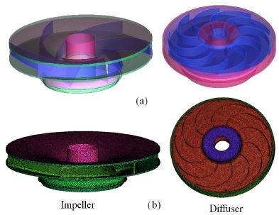
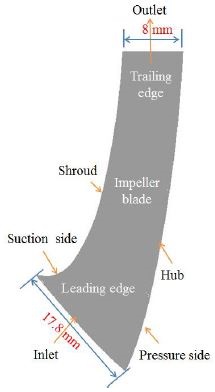
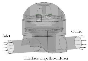
Fig. 1(a) represents the model pump of impeller and diffuser. The model pump was meshed by ANSYS ICEM-CFX. The model pump with impeller, diffuser and casing were meshed and a mesh dependency test (impeller and diffuser) was carried out under noncavitating conditions at the design operating flow (24 m3/hr) and found pressure drops error was less than 1%. The total meshed element and nodes were 4,477,248 and 1,417,827. The grid systems are shown in Fig. 1(b). Fig. 2 shows the meridional view of the impeller blade and it’s inlet and outlet dimensions. A frozen rotor was applied to couple the rotation and stationary domain(diffuser) for the steady state analysis. The computational pump domain is shown in Fig. 3. The inlet boundary was total pressure and mass flow rate was imposed at outlet boundary. All boundary walls were assumed smooth wall with no-slip condition.
High resolution for the advection scheme, first order for turbulence numeric and SIMPLEC algorithm were considered in solver setting. The residual value was of 1×10⁻⁵ controlled by convergence control solver. Table 1 shows the specification of centrifugal pump model for simulations.
3. Results and Discussion
3.1 Cavitation analysis
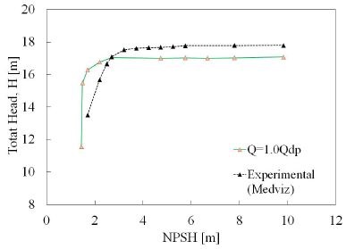
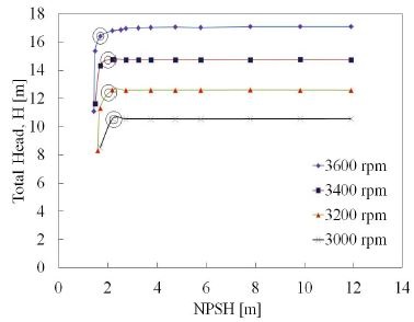
The NPSH is the head difference between absolute stagnation pressure in flow at the pump suction and the liquid vapor pressure. NPSHre which equals to NPSH3% is the minimum suction pressure necessary to ensure pump operation without cavitation. NPSH can be determined at specific flow rate. Fig. 5 is shown the total head versus net positive suction head. The black circle is represented the three percent of total head drop in the head drop line. If the pump would be operated under the required NPSH3%, there might be possible to form cavitation pitting on the impeller blade. Therefore, from the figure, with the changes of rotational speed there were small changes of NPSH3%, and pumps might be operated under good operating conditions. Figure 4 is shown a comparison of experimental and computed total head versus net positive suction head. The comparison of total head drops shown a good agreement.(6)
3.2 Rotational speed effects on cavitation
Fig. 5 is shown the total head versus net positive suction head for design flow rate (Qd.p.) at different rotational speeds. The head drop lines were obtained by reducing the suction pressure. From Fig. 5, the initial decrease of the NPSH had no effect on the head drop because the pump and total head remained unchained. When NPSH decreases, total head decrease and drops sharply at lower NPSH. The head drop varies for different rotational speeds. At design rotational speed of 3600 rpm, total head was constant and drops steeply at the value of 2.69 m. When the rotational speeds were gradually decreased the total head started to drop before the design rotational speed of 3600 rpm. At 3400 rpm the total head was started to drop at 3.19 m which was lager than the 3600 rpm. At 3200 rpm it began to drop at 2.71 m which was similar with the design rotational speed. At 3000 rpm the total head degraded to drop at 2.91 m. In the end the head drops sharply and the full cavitation or head breakdown occurred completely.
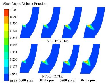
Fig. 6 is shown the cavitation effects on the meridional view of the impeller blade at different rotational speeds for design flow rate. The vapor volume fraction contours is from 0-1. From figure, it can be seen that the development of cavitation is changes with the changes of rotational speed. For NPSH=3.71 m, the propagation of cavitation was started from the suction shroud leading edge. The length of the cavity was increased from 3000 rpm to 3600 rpm. But for lower rotational speed the length of cavitation was lees affected at suction shroud than that of 3600 rpm.
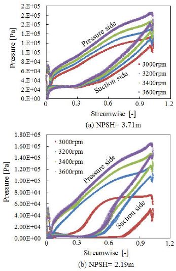
The pressure load distribution is one of important for cavitation analysis because there is directly effect on cavitation conditions and it’s related to the static pressure of the pump. Fig. 7 is illustrated the pressure distribution at design flow rate at different NPSH values for different rotational speeds. The impeller loading is the pressure difference between the static pressure on the pressure zone and the suction zone. The length of the low-pressure zone, where p<pv determines the extent of the cavitation region. From Fig. 7 the streamwise (0-1.2) location is the dimensionless distance from the inlet to outlet of the impeller. From Fig. 7(a), at NPSH=3.71 m the pressure distribution was affected on the suction side of the impeller, reducing the suction effect near the blade leading edge. It can be seen in Fig. 7(a) that the total head is not affected by cavitation. As the length of the cavity progresses (NPSH=2.19 m), eventually a condition is reached in which the blade work is impaired. In this case, when the cavity length on the blade suction surface exceeds the blade incidence and a part of the throat region blocks the impeller inlet as shown in the Fig. 7(b). When the value of NPSH decreases into 2.19 m, the pressure at the suction side (leading edge) was affected by the development of cavitation due to the suction leading effect. Fig. 7(b) shows that at NPSH=2.19 m, the pressure distribution effect almost same from 3600 rpm to 3200 rpm. But for the lower rotational speed (3000 rpm) the pressure upstream was reduced from streamwise (-) 0 to 0.8 than the others rotational speed. Therefore with the changes of rotational speed and lowering the NPSH there could have possibility to occur cavitation erosion earlier. At head breakdown, it could be observed that cavitation also appears on the inlet part of the blade pressure side.
3.3 Temperature effects on cavitation
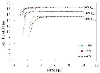
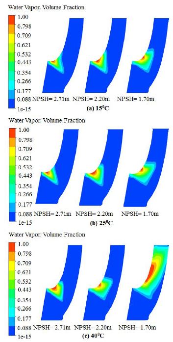
The development of cavitation is also be affected by thermodynamic effects. Therefore, that a change in temperature of the pumped liquid would affect the vapor pressure and therefore the NPSH. The effect that relates to the mechanism of heat and mass transfer associated with cavitation. Fig. 8 is illustrated this effect for water pumped at three different temperatures (15℃, 25℃ and 40℃) for three different flow rates. The graph is shown that pumping high temperature water requires high NPSH. It can be seen from the figure, cavitation breakdown decreases substantially with increasing temperature. At design flow rate the head drops steeply at lower NPSH for various temperatures but for the high temperature it’s drops earlier than other two different temperatures (15℃, 25℃). In the end the head drops gradually decrease or head break down occurred. Therefore, liquid-vapor phases flow prevails in the large portion of the impeller blades. At lower temperature cavitation is occurred at lower NPSH but at higher temperature it is occurred at higher NPSH, that means higher temperature might have possibility to occur quickly cavitation erosion on the impeller blade than the lower temperature. This thermal effect can be extended to attached or blade cavities with a changes in details as shown in Fig. 9. Fig. 9 is shown the cavitation development effect in the meridional view on the impeller blade at three different temperatures with three different net positive suction head. It is implies that, at NPSH=2.71 m, the development of cavitation was almost same for the three various temperatures (15℃, 25℃ and 40℃) but for the NPSH=2.20 m the cavitation had less effected at 15℃ than the others and at 40℃ the region of cavitation was increased from shroud to hub side. Finally for NPSH=1.70 m, the full cavitation or completely head breakdown occurred at 40℃ and seen that the blade cavity region was completely obstructed, which could block the internal circulation flow of the model pump.
4. Conclusion
The head drop curves are obtained for different rotational speeds and the performances were described according to the NPSH. Also the development of cavitation performances were estimated and described by the thermodynamic effects. The attached cavitation on the impeller blade from suction leading edge to trailing edge was observed according to the various speeds and temperatures. It was found that cavitation erosion occurred quickly at higher temperature than the lower temperature.
Acknowledgments
2015 한국유체기계학회 동계 학술대회 발표 논문, 2015년 12월 2일~12월 4일, 제주
References
-
LIU, H-l., LIU, D-X., WANG, Y., Wu, X-F., and Wang, J., (2013), “Experimental Investigation and Numerical Analysis of Unsteady Attached Sheet Cavitating Flows in a Centrifugal Pump”, J. of Hydrodynamics, Vol. 25, p370-378.
[https://doi.org/10.1016/s1001-6058(11)60375-3]

- Pumping Station Engineering Hand Book, (1991), “Japan Association of Agriculture Engineering Enterprises”, Tokyo.
- Brennen, C. E., (1994), “Hydrodynamics of Pumps, Concepts ETI, Inc”, USA and Oxford University press, England.
- Fard, M. P., and Roohi, E., (2008), “Transient Simulations of Cavitating Flows using a Modified Volume of Fluid (VOF) Technique”, Int. J. Computational Fluid Dynamics, Vol. 22(No. 1~2), p97-114.
-
Bakir, F., Rey, R., et al. , (2004), “Numerical and Experimental Investigations of the Cavitating Behavior of an Inducer”, International Journal of Rotating Machinery, Vol. 10, p15-25.
[https://doi.org/10.1080/10236210490258034]

-
Medvitz, R. B., Kunz, R. F., et al. , (2002), “Performance Analysis of Cavitating Flow in Centrifugal Pumps using Multiphase CFD”, Journal of Fluids Engineering, Vol. 124, p377-383.
[https://doi.org/10.1115/1.1457453]

- Bruno, S., and Frank, C. V., (2009), “Pump Cavitation- Various NPSHR Criteria, NPSHA Margins, and Impeller Expectancy”, Proceedings of the Twenty Fifth International Pump users Symposium, p113-144.
