Effect of the Hub to Tip Diameter Ratio to the Performance of a Bulb Hydro Turbine Model
Abstract
The hub to tip diameter ratio (HTR) is one of the important factors that affects the performance of a bulb turbine. However, studies on this parameter are limited. Understanding the influence of the parameter on the performance of a bulb turbine can provide designers with useful information to improve turbine performance. Therefore, this study investigates the effect of HTR on the performance of a bulb hydro turbine model using CFD analysis. The performance characteristics of the bulb turbine model demonstrated that the turbine discharge decreased by 1.86%, the turbine hydraulic power decreased by 1.3%, and turbine efficiency maintained at the local maximum efficiency point condition when the HTR increased from Case 1 to Case 2. The results of loss analysis indicated that only different hydraulic loss between Case 1 and Case 2 came from the change in the HTR. An analysis on internal parameters, namely, cross-sectional area, axial velocity, change in the circumferential velocity through the runner domain, and hydraulic loss in the runner domain of both cases was performed to understand the turbine performance with varying HTR.
Keywords:
Bulb hydro turbine model, Performance characteristics, Hub to tip diameter ratio (HTR), Loss analysis, Computational Fluid Dynamic (CFD) analysis키워드:
벌브형 수차 모델, 성능 특성, 허브 직경비, 손실분석, CFD 분석1. Introduction
Bulb turbines have been widely used for low-head hydropower stations. A bulb turbine unit is characterized by axial flow passage, large discharge, high specific speed and compact structure. Many studies in the past have been conducted on design and investigation of flow characteristics of bulb turbines (1-6). Li F. et al. (7) designed runner blades and guide vanes of a bulb turbine by theoretical method. Yang W. et al. (8) optimized runner blades in a bulb turbine based on numerical simulation. Zhu L. et al. (9) designed and experimentally tested a low-head bulb turbine. Sing P. et al. (10) compared the untwisted blade and twisted blade according to performance of a low-head axial turbine. In another study, Sing P. et al. (11) investigated experimentally effect of exit blade geometry to performance of a small propeller turbine. The study analyzed the relationship between changes of blade geometry to internal flows of the turbine, which influences to turbine performance. For design of a horizontal bulb turbine, the hub to tip diameter ratio (HTR) is one of the important factors which could affect to turbine performance. However, the studies on this parameter have not been enough. The goal of the design is to maintain the turbine efficiency while changing the HTR. With this purpose, an investigation on the effect of the hub to tip diameter ratio to the performance and internal flow characteristics of a bulb hydro turbine model is conducted by Computational Fluid Dynamics (CFD) analysis.
2. Runner model and numerical method
2.1. Runner model
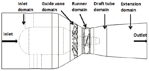
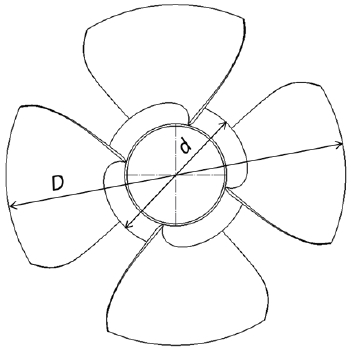
The bulb hydro turbine model is represented in Fig. 1. Dimensions of the runner model are introduced in Fig. 2. The four adjustable runner blades are mounted on the runner hub. Two bulb turbine models investigated in this study are only different from the HTR, which are indicated in Table 1. The class 115kW bulb turbine model operates under the design condition as effective pressure head of water across the turbine H = 12.5m, flow rate Q = 1.074 m3/s, and rotational speed n = 1800 min-1.
2.2. Numerical method
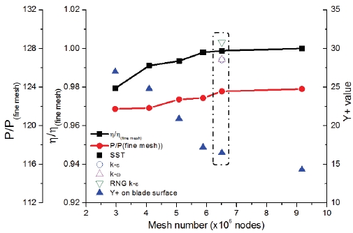
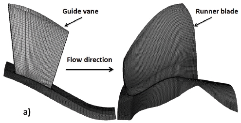
Nowaday, CFD analysis is an efficient method for investigating performance characteristics of a hydro turbine. The present study used a commercial CFD code of ANSYS CFX 18.1 (12) to solve the Reynolds- averaged Navier-Stokes equations. The mesh of whole fluid domains were generated using ANSYS 18.1 ICEM (12). A grid test was carried out according to different number of nodes as indicated in Fig. 3, which represents the relationship between the mesh grids, the normalized efficiency (η/η(fine mesh)), and hydraulic power (P/P(fine mesh)) by those of a fine mesh of the turbine model Case 1. A grid contained 6.5 million nodes is used for numerical calculation in the present study since the turbine performance has no change over this grid. The mesh of one pitch of the guide vane, runner blade (Case 1) and hub walls are constructed with the refined mesh in respect of the near wall treatment y+ value. The minimum y+ value in vicinity of the runner hub, leading, and trailing edges of the runner blade is 16.5 in the selected grid. As a turbulence model, the Shear Stress Transport (SST) turbulence model is used for all steady calculations in this study, since the SST turbulence mode is well known that it takes advantage of accuracy of k-ω model in the near wall regions and avoids the freestream sensitivity of the ω equation by replacing it with the ε equation in the farfield (13,14). Moreover, as a reference, the other three kinds of different turbulence models were adopted to examine the turbine efficiency at the design point and the results were shown relatively good agreement each other, regardless of the turbulence models as shown in Fig. 3. Table 2 presents numerical method for performance prediction of the turbine models.
3. Internal parameters analysis
In order to evaluate turbines performance characteristics of two turbine models, the internal parameters analysis is conducted at the LMEP condition by CFD analysis.
3.1. Turbine discharge
The turbine discharge is calculated by Equation (1). Here, A and Vm are cross-sectional area in the runner domain and axial velocity through the runner domain, respectively. The equation demonstrated the change in turbine discharge which depends on the change of individual value A or Vm or both of the values.
| (1) |
3.2. Hydraulic power
The hydraulic power (P) is a function of the theoretical Euler head (gHth), flow rate (Q), and fluid density (ρ) as indicated in Equation (2). Where, u is the peripheral velocity, and ΔVu = Vu1 - Vu2 is the change of circumferential velocity from inlet (indicator “1”) to outlet (indicator “2”) at the middle span of the runner blade of the flow through runner domain. The peripheral velocity is calculated at the same radius at inlet and outlet of the runner, thus u1 = u2 = u. The change of hydraulic power depends on changing of flow rate and change of circumferential velocity under constant rotational speed as indicated in Equation (2).
| (2) |
3.3. Hydraulic loss and efficiency
Equation (3) evaluates the total head (gH) by combination of the theoretical Euler head and hydraulic loss (hloss) in a turbine. The hydraulic loss consists of losses of all fluid domains as inlet (IL), guide vane (GV), runner (RN), draft tube (DT), and outlet domains (OL). The efficiency of a turbine is calculated as Equation (4) with consideration of the hydraulic loss.
| (3) |
| (4) |
4. Results and discussion
4.1. Performance curves
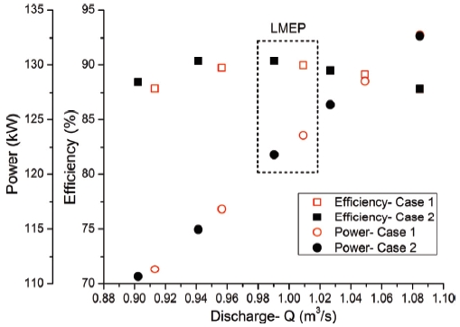
A comparison of performance characteristics of the bulb turbine models at various discharge conditions under design rotational speed is represented in Fig. 5. It obviously shown that, the turbine efficiency is maintaining at various discharge while changing the HTR. Hydraulic power and turbine discharge produced by Case 2 are lower than that of Case 1. An percentage analysis of major turbine parameters for two cases under constant design head at the LMEP condition is illustrated in Table 3. The turbine efficiency did not change despite of HTR’s changing at the LMEP condition. Thus, the internal flow analysis will be examined to understand the effect of HTR to the turbine performance.
4.2. Loss analysis
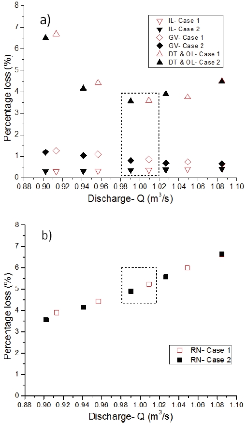
To figure out distributions of hydraulic loss in each fluid domain, the loss analysis of the two models are investigated by adopting Equations (5) and (6) on all fluid components.
| (5) |
| (6) |
Where Δp is the different pressure in the analyzed domain. T and ω is torque and angular velocity of the runner. Equations (5) and (6) are applied to calculate loss of static domains, and the rotating domain, respectively. The losses of fluid domains for two cases are indicated in Figs. 6(a) and (b). The Fig. 6(a) showed no different losses between Case 1 and Case 2 in all components at the LMEP condition. The only different loss between Case 1 and Case 2 came from the runner domain in Fig. 6(b) at the LMEP, bounded by dashed black lines. The bigger HTR, Case 2, had lower flow rate passing the turbine runner at the same operating condition. As a result, the hydraulic loss in the RN- Case 2 is lower than that of RN- Case 1 as illustrated in the Fig. 6 (b).
4.3. Internal parameters analysis
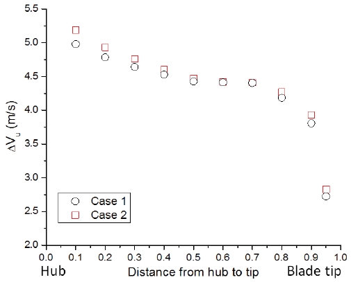
To understand the change of turbine performance and hydraulic loss in the runner domain, the internal parameters analysis was conducted at the LMEPcondition. By employing Equations (1) and (2) to analyze internal parameters for two turbine models, averaged parameters from span of 0.1 to 0.95 (from hub to blade tip) of Case 1 and Case 2 are indicated in Table 4. The HTR increases from Case 1 to Case 2 resulting in decreasing of cross-sectional area by 4.37% and increasing of axial velocity by 2.61%. Subsequently, the discharge reduces approximately 1.86% as seen in Tables 3 and 4. The change in circumferential velocity through the runner is increased by 0.59% as increasing of the HTR. Decrease of flow rate from 1.0076 m3/s to 0.9889 m3/s and increase of change in circumferential velocity from 4.355 m/s to 4.381 m/s led to growth of 1.3% hydraulic power from Case 2 to Case 1 by using Equation (7).
| (7) |
4.4. Velocity triangle components distribution
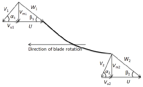
The velocity triangles distribution at the entrance and exit of the blades are important factors for design a turbomachinery (15). It is investigated to evaluate the influence of the hub to tip ratio to the turbine performance. Fig. 7 shows the schematic of velocity triangles at the blade entrance and exit. In the figure, α is the absolute angle that is between absolute velocity (v) and rotor tangential velocity (u). β is the runner blade angle that is between relative velocity (w) and u. Indicators 1 and 2 refer to the inlet and outlet of the runner blade, respectively. For well-designed runner blade, the flow angle through guide vane should be as close as to the inlet angle of runner blade, the downstream flow of water should not exist swirl flows(16). In both cases, the blade angle and guide vane angles are adjusted at 20 degrees and 61.5 degrees, respectively. Table 5 indicated flow angles at relative span of 0.2. Depending on the HTR, the positions of span of 0.2 are a little different in Cases 1 and 2. The runner inlet and outlet angles are slightly increase, the absolute angles at runner inlet and outlet are also close to the ideal angles (90°) as Case 2.
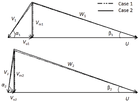
Entrance and exit velocity diagrams (upper and bottom of the figure) for runner blade at relative span of 0.2
4.5. Streamline and components velocity coefficient distribution
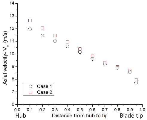
The streamline distributions on the pressure side of the runner blade of two cases at LMEP condition are shown in Fig. 9. The flow angles at runner blade inlet and outlet of the span of 0.2 are closer to the runner blade angle and ideal absolute outlet angle in Case 2 as seen in Table 5. Thus, more uniform streamline is found at the span of 0.2 and its vicinity area of Case 2. It contributes to reduce the hydraulic loss in the runner domain of Case 2 as indicated in Fig. 6(b). The axial velocity and change of circumferential velocity through the runner blade distribution from hub to blade tip are represented in Figs. 10 and 11. From a comparison of these velocity components between Case 1 and Case 2, it clearly points out that these velocity component values in Case 2 are higher than that of Case 1 in vicinity of the hub area.
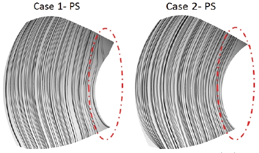
Streamline distribution on pressure side (PS) of the runner blade for two cases at the LMEP condition
5. Conclusions
The purpose of the present study is to maintain the turbine efficiency while changing the HTR at the design operating condition by CFD analysis. Therefore, two cases of HTR are investigated on effect of the HTR to the turbine performance and internal flow characteristics in the bulb turbine model at the LMEP condition. Based on the CFD result, the turbine efficiency is similar in both cases. Due to maintenance in term of turbine efficiency without change the runner blade angle, thus, the internal flow analysis has been conducted. The internal parameters analysis revealed that, increase of the HTR from Case 1 to Case 2 resulted to the change of optimal operating point. The flow angles at runner blade inlet and outlet are closer to the runner blade angle and ideal absolute outlet angle in Case 2. Therefore, the streamline distribution in vicinity of hub area of Case 2 is more uniform than that of Case 1.
Acknowledgments
This work was supported by the New and Renewable Energy of the Korea Institute of Energy Technology Evaluation and Planning (KETEP) grant funded by the Korea Goverment Ministry of Trade, Industry and Energy (No. 20163010060340).
References
-
Ferro, L. M. C, Gato, L. M. C., and Falcão, A. F. O, (2010), “Design and experimental validation of the inlet guide vane system of a mini hydraulic bulb-turbine”, Renewable Energy, 35, p1920-1928.
[https://doi.org/10.1016/j.renene.2010.01.020]

-
Li, L., Zheng, Y., Zhou, D., and Mi, Z., (2013), “Hydraulic characteristics of the new type bulb turbine with micro-head”, Proceedings of the ASME 2013 International Mechanical Engineering Congress and Exposition.
[https://doi.org/10.1115/imece2013-62936]

- Zheng, X. B., Zheng, X., and Ma, J. Y., (2013), “Optimum design of exit guide vane on the bidirectional tubular turbine”, IOP Conference Series: Materials Science and Engineering.
- Gehrer, A., Benigni, H., and Kostenberger, M., (2004), “Unsteady simulation of the flow through a horizontal-shaft bulb turbine”, 22th IAHR Symposium on Hydraulic Machinery and System.
- Duquesne, P., Maciel, Y., and Deschenes, C., (2016), “Investigation of flow separation in a diffuser of a bulb turbine”, Journal of Fluids Engineering, 138, p011102-1-011102-9.
-
Li, J., Li, B., Song, L., and Feng, Z., (2016), “Multidisciplinary optimization design of long blade turbine stage based on parallel self-adaptive multi-objective differential evolution algorithm”, Proceedings of ASME turbo expo 2016: Turbomachinery technical conference and exposition GT2016.
[https://doi.org/10.1115/gt2016-56180]

-
Li, F., Fan, H., Wang, Z., and Chen, N., (2011), “Coupled design and optimization for runner blades of a tubular turbine based on the boundary vorticity dynamics theory”, Proceedings of the ASME-JSME-KSME 2011 Joint Fluids Engineering Conference.
[https://doi.org/10.1115/ajk2011-22017]

-
Yang, W., Wu, Y., and Liu, S. H., (2011), “An optimization method on runner blades in bulb turbine based on CFD analysis”, Science China Technological Sciences, 54(2), p338-344.
[https://doi.org/10.1007/s11431-010-4261-4]

- Zhu, L., Zhang, H. P., Zhang, J. G., Meng, X. C., and Lu, L., (2012), “Performance of a bulb turbine suitable for low prototype head: model test and transient numerical method”, 26th IAHR Symposium on Hydraulic Machinery and Systems.
- Sing, P., and Nestmann, F., (2012), “Influence of the blade hub geometry on the performance of low-head axial flow turbines”, Journal of Energy Engineering, 138(03), p109-118.
- Sing, P., and Nestmann, F., (2010), “Exit blade geometry and part-load performance of small axial flow propeller turbines: An experimental investigation”, Experimental Thermal and Fluid Science, 34, p798-811.
- ANSYS Ins, (2017), “ANSYS CFX Documentation”, Ver. 18.1, http://www.ansys.com (2017).
-
Menter, F. R., (1994), “Two-Equation Eddy-Viscosity Turbulence Models for Engineering Applications”, AIAA Journal, 32(8), p1598-1605.
[https://doi.org/10.2514/3.12149]

-
Menter, F. R., (1993), “Zonal Two-Equation k-ω Turbulence Models for Aerodynamic flows”, AIAA Journal, 93-2906.
[https://doi.org/10.2514/6.1993-2906]

- Ingram, G., (2009), Basic Concepts in tubomachinery, Bookboon.
-
Chen, Z., Singh, P. M., and Choi, Y-D., (2016), “Francis turbine blade design on the basic of port area and loss analysis”, Energies, 9, p164.
[https://doi.org/10.3390/en9030164]

