Effects of Impeller Blade Shape and Impeller Disk Side Gap Passage Shape on the Regenerative Blower Performance
Abstract
Regenerative blowers can produce a high head with a small flow rate, which makes them desirable compared to positive displacement pumps. The regenerative blower consists of an impeller and casing. The impeller shape contributes to the performance of the regenerative blower. CFD analysis is conducted to investigate the effect of geometrical modification on the operating condition of regenerative blowers like head, power, and efficiency. The geometry modification of the regenerative blower is achieved by varying the impeller blade curvature radius, blade inclination angle, blade shape (curved, radially straight, and chevron), and impeller disk side gap passage shape. The various impeller blades and impeller disk side gap passage designs were selected and conducted the CFD analysis to evaluate the regenerative blower performance and internal flow behavior. Study results show that changing the blade shape from curved to radially straight type can improve the blower’s performance.
Keywords:
Regenerative blower, Impeller blade shape, Impeller disk side gap passage shape, Blade inclination angle, Performance키워드:
재생형 블로워, 임펠러 블레이드 형상, 임펠러 디스크 측면 틈새 유로 형상, 블레이드 경사각도, 성능1. Introduction
Regenerative blowers are used for low specific speed turbomachines, which generate high heads at low flow rates. Typically regenerative blower consists of an impeller, inlet port, discharge port, stripper, and casing. The impeller blades are designed in such a way that it produces a series of helical flows in the casing and return to the impeller multiple times. Fluid enters the flow channel through the inlet port, which is shaped to set up a spiral flow around the annular channel. The impeller blade creates the circulation flow in the flow passages to increase the pressure from the inlet to the discharge ports. The clearance between the impeller and casing is kept minimum to prevent leakage from the high-pressure side to the low-pressure side(1).
Regenerative blowers are unpopular for their efficiencies because the circulatory flow pattern causes various losses. The typical efficiency of regenerative blower is less than 50%, but simple construction, stable operating characteristics, reliability, compact size, and low maintenance increase their desirability for various purposes(2). The regenerative blower is used in the flow circulator in the wastewater treatment plant, BOP of the fuel cell system, automobiles, medical equipment, and so on(3). The turbulent mixing theory(4), shear stress theory(5), and momentum exchange theory(6) are used to explain the flow mechanism of regenerative turbomachines. Badami compared the momentum exchange theory with experimental data(7). Yoo suggested the improved momentum exchange theory to predict the complicated helical flow in regenerative turbomachines(8). Won et al. found that the head coefficient and efficiency depend on the blade’s geometry shape(9). Vasudeva Karanth et al. studied the effect of the inlet and outlet passages on the performance of regenerative pumps(10). The curvature in the outlet flow passage increases the net pressure head by reducing vortex flow and rotating stall(11). Jafar Nejad investigated the effect of inlet port curvature on the regenerative pump performance(12).
Chan Lee used CFD analysis methodology to compare the internal flow of the various types of regenerative blowers and concluded that CFD analysis was used to develop a new and efficient blower for fuel cell application(13). The blade thickness, hub height, and blade bending angle are used for optimization(14). Fleder et al. conducted CFD analysis on various geometrical shapes of regenerative turbomachines(15). Nejadrajabli modified blade geometry according to the blade angle to improve the regenerative flow pump performance(16). It is possible to predict the blade number influence in the head coefficient with more accuracy than efficiency(17). The flow between impeller blades caused pressure fluctuation in the regenerative turbomachines(18).
The study objective is to determine the various parameters that influence the performance of regenerative blower. The impeller blade shapes were modified according to blade curvature and inclination angle. The impeller and impeller disk side gap passage shapes are used to confirm and improve the performance curves of a regenerative blower.
2. Modeling and Methodology
2.1 Regenerative blower design
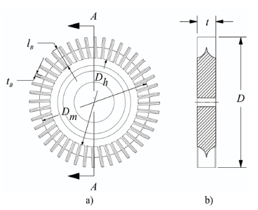
Fig. 1 shows the impeller blade and cross-section view of the casing flow passage. The flat surface casing is used for simplification of the casing design. The impeller shape plays a vital role in the performance of the regenerative fluid machinery. Fig. 2 shows a 2D drawing of a regenerative blower with a straight-type impeller. The basic design dimension is indicated in Fig. 2.
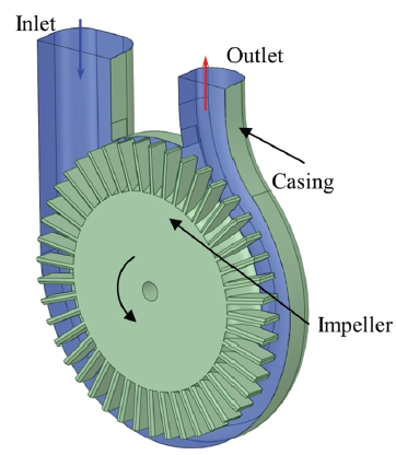
3D model of regenerative blower impeller (radially straight) and cross-section view of casing flow passage
The regenerative blower consists of an impeller and casing. The design specification of the regenerative blower is shown in Table 1. The regenerative blower performance is dependent on the design specification. The dimensions for the design of the regenerative blower are tip diameter (D), hub diameter (Dh), mean diameter (Dm), impeller thickness (t), blade thickness (tb), and blade length (bl). The impeller dimensions are normalized using tip diameter.
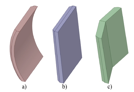
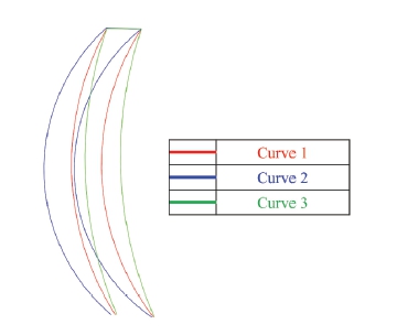
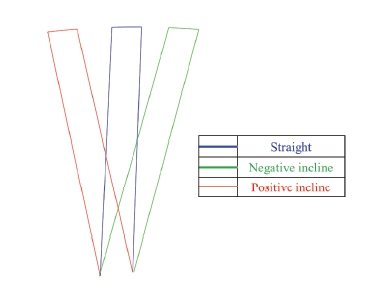
Fig. 3 shows three types of impeller shapes. The curved, radially straight, and chevron types of impeller blades are selected to evaluate their performance. A detailed study of the blade shape was carried out. Fig. 4 indicates the three types of blade curvature. The blade curvature is determined by the radius of curvature (r). The various inclination angles were used to evaluate the regenerative blower performance. Fig. 5 indicates the inclination angle of the radially straight blade. The positive and negative inclination angle was determined according to the impeller rotation direction. The four types of impeller disk leakage gaps were designed, as shown in Fig. 6. The detailed information on the curvature and inclination angle of the impeller blade is shown in Table 2. The leakage 1 model is an initial shape of the regenerative impeller disk leakage gap. The leakage gaps are installed only on both side walls of the impeller disk, but the casing disk side wall is a flat surface.
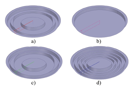
Various impeller disk gap for regenerative blower a) leakage 1 b) leakage 2, c) leakage 3 and d) leakage 4
The dimensionless terms were used to evaluate the performance of the regenerative fluid machinery(19).
| (1) |
| (2) |
| (3) |
where λ is head coefficient, ϕ is flow coefficient, ω is rotational speed (rad/s), D is impeller outer diameter (m), ρ is density of fluid (kg/m³), g is acceleration due to gravity (m/s²), Q is flow rate (m³/s), H is effective head (m), τ is torque consumed by impeller (Nm).
2.2 Numerical methodology
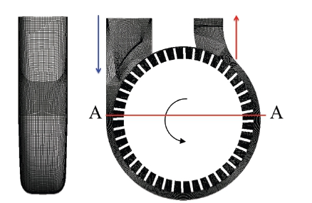
The numerical analysis was performed to investigate the performance and internal flow behavior according to the impeller and impeller disk leakage shapes. CFD analysis was conducted by using the commercial code of ANSYS-CFX 2021R1(20). The ANSYS ICEM 2021R1(20) is used to generate hexahedral numerical grids for the CFD analysis, as shown in Fig. 7. The y+ wall near the wall of the impeller and casing is maintained below 5.
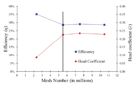
Fig. 8 shows the mesh dependency test for the selection of the optimum node number. According to the mesh dependency test, a 5.5 million node number is suitable for the stable CFD analysis. The further increase in the mesh number does not influence on the CFD analysis results. The steady-state conditions and air at 25°C are used in the analysis. The shear stress transport turbulence model is used for the CFD analysis. The static pressure and mass flow rate are used as inlet and outlet boundary conditions, respectively. The frozen rotor was selected for the interface between the impeller and casing wall.
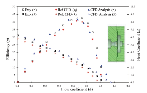
The reference experimental and CFD analysis data were adopted from the study of Quail(21) to validate the current CFD methodology. The geometrical shape of the Quail(21) impeller is shown in Fig. 9. The reference experimental and CFD analysis results match well with the current CFD analysis data. It implies that the current CFD methodology is acceptable for the further analysis of regenerative blower.
3. Results and Discussion
3.1 Performance curves of regenerative blower
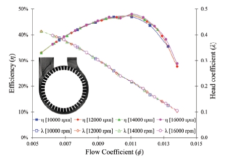
Fig. 10 shows the performance curves of an initial regenerative blower model with a straight impeller blade and the impeller disk leakage gap 1 according to the various rotational speeds. The efficiency of the regenerative blower is 48% with a radially straight impeller blade. The head coefficient of regenerative blower are 0.41 and 0.01 at ϕ=0.005 and ϕ=0.104, respectively. The efficiency and head coefficient of regenerative fluid machinery is relatively constant with rotational speed variation, and the similarity law of the performance matches well.
3.2 Internal flow of regenerative blower
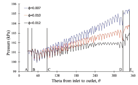
The regenerative blower increases pressure from the inlet to the outlet due to the circulatory flow pattern. Fig. 11 indicates that the absolute pressure increases from the inlet to the outlet of the regenerative blower. The pressure distribution from the inlet to the outlet of the regenerative blower depends on the flow coefficient. At ϕ=0.007, the outlet pressure is highest compared to ϕ=0.012. Hence, at partial flow conditions, outlet pressure is much higher than the inlet pressure. Fig. 11 represents the four sections in the regenerative fluid machinery from inlet to outlet. In inlet region AB, the flow experiences some pressure loss. When the flow enters the BC region, the pressure remains constant and begins to accelerate. The CD is the linear region with a constant pressure gradient. The DE is the decelerated region in which the kinetic energy of the circulatory velocity decreases and increases pressure. The flows exit from the outlet region with minor losses.
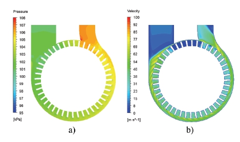
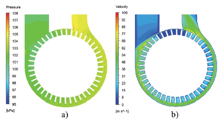
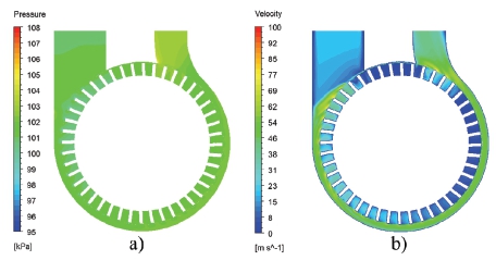
The internal flow behavior in the regenerative blower is explained using pressure and velocity contours. Figs. 12-14 represent the pressure and velocity contours in the regenerative blower at various flow coefficients. It implies that the static pressure increases gradually from the inlet to the outlet. At ϕ=0.006, the static pressure increases drastically from the mid-section of the regenerative blower, and flow velocity ranges from 30 m/s to 35 m/s. At ϕ=0.011, the static pressure increases gradually without any drastic rise in static pressure, as in ϕ=0.006. At ϕ=0.011, the drop in the velocity magnitude is visible compared to ϕ=0.006. At ϕ=0.014, the static pressure is approximately the same throughout the impeller region, and pressure rise is minimum. At the end of the linear region, the slight pressure drop is visible at ϕ=0.014. The velocity at the wall of the casing is relatively higher throughout the impeller section. The difference in velocity magnitude is visible at the casing wall and impeller section.
3.3 Influence of blade curvature on the regenerative blower performance
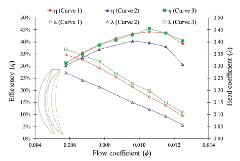
The impeller blade shape is the most vital design parameter for the performance of a regenerative blower. The various blade curvature radius is used to compare the regenerative blower performance. Fig. 15 represents the performance curves comparison between impeller blades with numerous radii of blade curvature. The impeller blade with curve 2 has relatively lower efficiency than curves 1 and 3. When r/D tends to infinity, the blade shape becomes a radially straight blade. When r/D is low, the impeller blade curvature is high. It indicates that the larger radius of blade curvature is suitable for the regenerative blower.
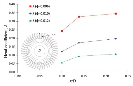
Fig. 16 indicates the relationship between the radius of blade curvature and the head coefficient. The blade curvature radius is divided by the impeller diameter to obtain a normalized value. Fig. 16 implies that the decrease in the radius of blade curvature gradually drops in head coefficient till the critical radius value. The further reduction in the radius of blade curvature beyond critical value causes a significant drop in head coefficient. At ϕ=0.006, the head coefficient drop is more significant than in ϕ=0.012. It concludes that the radially straight blade shape is better than the curved blade shape.
3.4 Influence of blade inclination on the regenerative blower performance
The radially straight blade type is commonly used for the blower impeller design. The blade inclination angle is examined to confirm the performance of the regenerative blower. The positive and negative inclination corresponds to the impeller rotation direction.
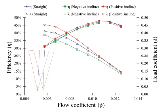
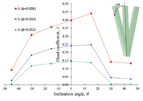
Fig. 17 shows the comparison of various inclination angle performance curves. The difference in efficiency with the change of inclination angle is minimum. However, the difference in head coefficient is significant. Fig. 18 shows the variation of the inclination angle with the head coefficient. The head coefficient decreases drastically when the inclination angle is more than +30° and less than -30°. The best inclination angle is in the range of +10° to +20°. The head coefficient decreases linearly from +15° to –30°. Fig. 18 implies that the inclination angle should incline with impeller rotation.
3.5 Influence of blade types on the regenerative blower performance
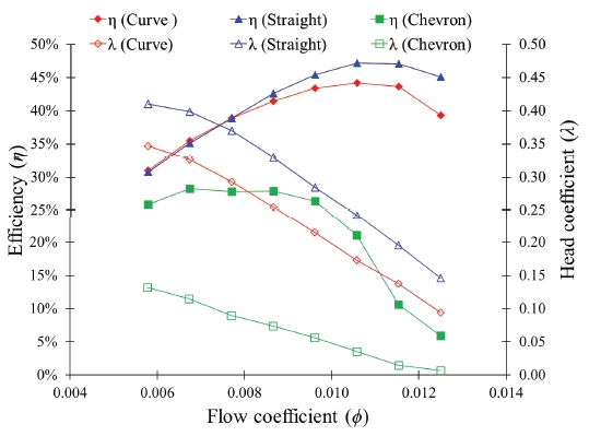
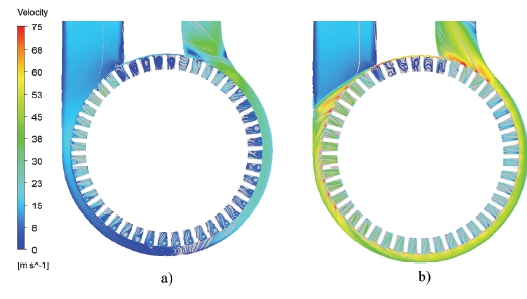
The performance of a regenerative blower depends on the impeller blade type. The proper blade type helps to improve the performance of the regenerative blower. The performance curves of the curved, radially straight, and chevron-type blade shapes are compared in Fig. 19. The straight-type blade type shows a maximum efficiency of 47%, whereas the maximum efficiency achieved by the curve and chevron blade types are 44% and 27%, respectively. It indicates a difference of 20% between the two blade types. Fig. 20 shows the velocity streamlines in the impeller flow passage of chevron and straight-type blade shapes at mid-section. The straight-type impeller blade shape shows a better and smooth flow field compared to the chevron type. The amount of eddies and recirculation flow in the impeller passage of chevron type blade is high, which reduces the pressure and increases losses. Therefore, a significant drop in efficiency is visible in the chevron-type impeller. Hence, it concludes that the proper blade type design improves the regenerative blower performance efficiently.
3.6 Influence of impeller disk side gap passage shape on the regenerative blower performance and internal flow
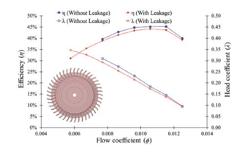
The impeller disk side gap passage shape of the regenerative blower is simple in design, but it directly changes the leakage gap shape. Fig. 21 shows the efficiency drop in the regenerative blower with and without leakage 1. Without leakage type is designed only for CFD analysis and comparison purposes and does not exist in actual operating conditions. The maximum 2% efficiency drop is calculated in the regenerative blower with a leakage gap 1.
In order to investigate the reason for the efficiency drop by the side leakage gap, internal streamlines of the leakage gap between the casing and impeller side walls are examined, as shown in Fig. 22. The internal flow analysis result shows that the flow pattern in the leakage gap makes strong through flow between the inlet and outlet section of the regenerative blower, which results in the pressure loss in the blower passage. A detailed investigation of the leakage gap was carried out by modification of the impeller disk side shape.
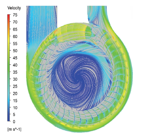
Internal streamlines through the impeller disk side gap passage shape of leakage 1 at ϕ=0.011 by CFD analysis
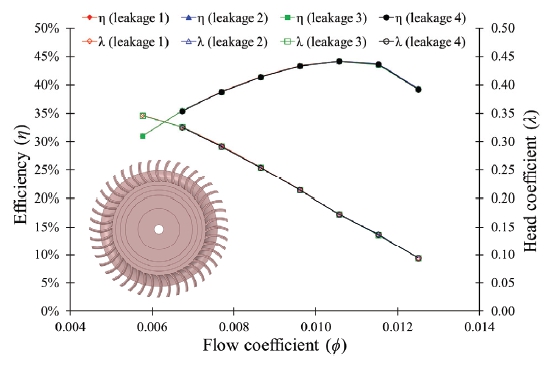
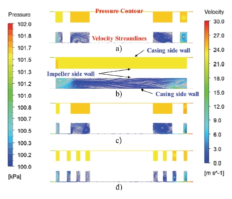
According to the impeller disk side shape, four types of leakage gaps are available for the study. Fig. 23 indicates the performance curves of the regenerative blower with various leakage passage shapes in the impeller disk side gap. The results show that the performance curves of the regenerative blower are independent of the impeller disk side leakage gap shape in this study.
Fig. 24 shows the pressure contours and velocity streamlines in the mid-section, which is indicated as the A-A line in Fig. 7, of the regenerative blower. The leakage 2 is the simple plane shape without any labyrinth structure. The other leakage gap shapes possess a labyrinth structure that prevents mixing the high and low-pressure fluids in the leakage gap. In leakage gaps 1 and 3, the circulation flow is visible within the leakage gaps due to the large labyrinth shape. The leakage gap 4 has numerous small labyrinth structures, which suppress the mixing and circulation flow in the leakage gap flow passage. The pressure distribution is approximately the same throughout the leakage flow passage. However, in order to suppress the leakage loss through the leakage gap between the casing and impeller side walls, more detailed and efficient structures of labyrinth shape should be considered.
4. Conclusions
The impeller blade shape and impeller disk side gap passage shape that influence the performance of the regenerative blower were examined. The various impeller blade shapes of the regenerative blower were analyzed using CFD analysis. The curved, radially straight, and chevron-type blade shapes were used in the study.
The impeller blade shape is the influence parameter for the performance of the regenerative blower. The curved and radially straight blade shapes showed relatively better performance than the chevron blade type. The curvature of the impeller blade affects the performance of the regenerative blower significantly. The head coefficient of the regenerative blower decreases with increases in the curvature radius. Among the three types of blade shapes, the straight-blade impeller type showed higher best efficiency than the other two blade shapes. Furthermore, the various inclination angles of the straight-blade impeller type were investigated, and the inclination angle of 10° to 20° is the most preferable for the high head coefficient. The curvature and inclination angle for the proper impeller blade design should be radius ratio, r/D > 0.2 and –20° < inclination angle, θ < +20°, respectively.
The leakage loss through the impeller disk side gap passage is more than 2% in the regenerative blower. The increase in the width labyrinth number helps to reduce the recirculation flow in the regenerative blower, but more detailed and efficient structures of the labyrinth shape should be considered to suppress the leakage loss more.
Acknowledgments
본 과제(결과물)는 2023년도 교육부의 재원으로 한국연구재단의 지원을 받아 수행된 지자체-대학 협력기반 지역혁신사업의 결과입니다. (재단 과제관리번호 : 광주전남플랫폼 2021RIS-002)
References
-
Sixsmith, H., and Altmann, H., 1977, “A regenerative compressor,” Journal of Engineering for Industry, Vol 99, No. 03, pp. 637-647.
[https://doi.org/10.1115/1.3439291]

-
Raheel, M. M.,and Engeda, A., 2005, “Systematic design approach for radial blade regenerative turbomachines,” J Propul Power, Vol. 21, No. 5, pp. 884-892.
[https://doi.org/10.2514/1.1426]

-
Jang, C., and Jeon, H., 2014, “Performance enhancement of 20kW regenerative blower using design parameters,” International Journal of Fluid Machinery and Systems, Vol. 7, No. 3, pp. 86-93.
[https://doi.org/10.5293/IJFMS.2014.7.3.086]

-
Senoo, Y., 1956, “A comparison of regenerative pump theories supported by new performance data,” Transactions of the American Society of Mechanical Engineers, Vol. 78, No. 5, pp. 1091-1095.
[https://doi.org/10.1115/1.4013932]

-
Iversen, H. W., 1955, “Performance of the periphery pump,” Transactions of the American Society of Mechanical Engineers, Vol. 77, No. 1, pp. 19-22.
[https://doi.org/10.1115/1.4014210]

-
Wilson, W. A., Santalo, M. A., and Oelrich, J. A., 1955, “A theory of the fluid-dynamic mechanism of regenerative pumps,” Transactions of the American Society of Mechanical Engineers, Vol. 77, No. 8, pp. 1303-1311.
[https://doi.org/10.1115/1.4014671]

-
Badami, M., 1997, “Theoretical and experimental analysis of traditional and new periphery pumps,” SAE Technical Paper, No. 971074.
[https://doi.org/10.4271/971074]

-
Yoo, I. S., Park, M. R., and Chung, M. K., 2005, “Improved momentum exchange theory for incompressible regenerative turbomachines,” Proc Inst Mech Eng A: J Power Energy, Vol. 219, No. 7, pp. 567-581.
[https://doi.org/10.1243/095765005X31252]

-
Choi, W. C., Yoo, I. S., Park, M. R. et al., 2013, “Experimental study on the effect of blade angle on regenerative pump performance,” Proc Inst Mech Eng A: J Power Energy, Vol. 227, No. 5, pp. 585-592.
[https://doi.org/10.1177/0957650913487731]

- Vasudeva Karanth, K., Manjunath, M. S., and Sharma, Y. N., 2015, “Numerical study of a self priming regenerative pump for improved performance using geometric modifications,” International Journal of Current Engineering and Technology, Vol. 5, No. 1, pp. 105-109.
- Maity, A., Chandrashekharan, V., and Afzal, M. W., 2015, “Experimental and numerical investigation of regenerative centrifugal pump using CFD for performance enhancement,” International Journal of Current Engineering and Technology, Vol. 5, No. 4, pp. 2898-2903.
-
Nejad, J., Riasi, A., and Nourbakhsh, A., 2017, “Parametric study and performance improvement of regenerative flow pump considering the modification in blade and casing geometry,” Int J Numerical Methods Heat Fluid Flow, Vol 27, No. 8, pp. 1887-1906.
[https://doi.org/10.1108/HFF-03-2016-0088]

-
Lee, C., and Kil, H. G., 2014, “The design, performance and CFD analyses of regenerative blower used for fuel cell system,” In: Anonymous 2014 4th international conference on simulation and modeling methodologies, technologies and applications (SIMULTECH) IEEE, pp. 751-755.
[https://doi.org/10.5220/0005104007510755]

-
Jang, C., and Han, G., 2010, “Enhancement of performance by blade optimization in two-stage ring blower,” Journal of Thermal Science, Vol. 19, pp. 383-389.
[https://doi.org/10.1007/s11630-010-0398-5]

-
Quail, F. J., Scanlon, T., and Baumgartner, A., 2012, “Design study of a regenerative pump using one-dimensional and three-dimensional numerical techniques,” European Journal of Mechanics-B/Fluids, Vol. 31, pp. 181-187.
[https://doi.org/10.1016/j.euromechflu.2011.06.003]

-
Nejadrajabali, J., Riasi, A., and Nourbakhsh, S. A., 2016, “Flow pattern analysis and performance improvement of regenerative flow pump using blade geometry modification,” International Journal of Rotating Machinery, Vol. 2016, No. 8628467, pages 16.
[https://doi.org/10.1155/2016/8628467]

-
Fleder, A., and Böhle, M., 2019, “A systematical study of the influence of blade number on the performance of a side channel pump,” Journal of Fluids Engineering, Vol. 141, No. 11.
[https://doi.org/10.1115/1.4043166]

-
Zhang, F., Appiah, D., and Zhang, J. et al., 2018, “Transient flow characterization in energy conversion of a side channel pump under different blade suction angles,” Energy, Vol. 161, pp. 635-648.
[https://doi.org/10.1016/j.energy.2018.07.152]

-
Hollenberg, J. W., and Potter, J. H., 1979, “An investigation of regenerative blowers and pumps,” Journal of Engineering for Industry, Vol. 101, pp. 147-152.
[https://doi.org/10.1115/1.3439487]

- ANSYS, ANSYS CFX Documentation, ANSYS. Inc, Pennsylvania, (2021).
- Quail, F. J., 2009, “Design study of a regenerative pump using numerical and experimental techniques,” Thesis, University of Strathclyde, Glasgow.
