Effect of Shaft Sleeve Design on the Hydraulic and Suction Performances of Two-stage Centrifugal Pump
Abstract
Multistage centrifugal pumps are designed for industrial purposes to satisfy high head requirements. The two-stage centrifugal pump is used for specific industrial purposes. The impellers in the two-stage centrifugal pump are arranged in an opposite direction, and crossover guides the flow from 1st stage to 2nd stage impellers. The numerical analysis is performed to evaluate the performance of a two-stage centrifugal pump. The shaft sleeve design is modified from an edge to a curved type for better flow behavior. The numerical analysis showed that the modified shaft sleeve shape improves the pump’s hydraulic and suction performances, as well as internal flow behavior in a wide operation range. Besides the pump performances, the modified shaft sleeve shape showed structural stability with a relatively large margin below the ultimate tensile stress.
Keywords:
Two-stage centrifugal pump, Shaft Sleeve, Hydraulic performance, Suction performance, Internal flow, Structural stability키워드:
2단 원심펌프, 축슬리브, 수력성능, 흡입 성능, 내부유동, 구조 안정성1. Introduction
Multistage centrifugal pumps are used in industrial enterprises. Many industries use the multistage centrifugal pump to transfer fluid from low to high pressure. The demand for the multistage centrifugal pump has been high in industrial sectors for its wide range of operations. The centrifugal pumps consumed about 20% of global total energy(1). The design of the impeller is the same as that of the centrifugal pump. The design of multistage centrifugal should be compact. McKee et al.(2) reviewed the failure mechanism of the centrifugal pump. The probability of failure in a multistage centrifugal pump is relatively high. The multistage pump operates at high fluid pressure, which causes structural instability and failure.
Shojaeefard et al.(3) have indicated the different design parameters of the centrifugal pump that can influence the pump performance. Marathe et al.(4) have used numerical analysis to determine the performance characteristics of the multistage centrifugal pump. Cui and Li investigated the energy loss in the centrifugal pump based on the SST turbulence model(5). Kim et al. designed the ultra-low specific speed centrifugal pump and validated its feasibility using CFD analysis(6). The outlet position of the splitter blade showed a significant impact on the performance of the centrifugal pump(7). Onari and Arzani indicated the vulnerability of the shaft against repetitive vibration from the impeller of the multistage pump(8). The impeller blade is most vulnerable to mechanical failure.
Cavitation is a common physical phenomenon that occurs in turbomachinery. It is the process of formation of vapor bubbles in the low-pressure region in a centrifugal pump. The numerical analysis is helpful for the prediction of cavitation flow in the turbomachinery. Coutier-Delgosha experimented on the centrifugal pump to visualize cavitation and evaluate head drop in the impeller(9). Rayleigh-Plesset cavitation model helps to predict realistic cavitation in the turbomachinery(10). Lu et al. experimented to investigate the cavitation and vibration performance under a steady state(11). CFD analysis was performed to investigate the cavitation performance of an aviation fuel pump(12).
Chen et al. investigated the flow field and centrifugal pump performance according to the leading edge geometry(13). The higher blade wrap angle is better for the centrifugal pump efficiency(14). The blade inlet angle influenced the blade pressure and fluid recirculation in the single-blade centrifugal pump(15). The optimization techniques were implemented to improve the performance of the multistage centrifugal pump(16,17). The clearance gap between the shaft and sleeve bearing is a critical parameter that affects the dynamic characteristics of the shaft(18).
Several multistage centrifugal pump designs are available on the global market. In this study, the two impellers are arranged in an opposite direction. The proposed pump consists of a crossover to direct the flow from 1st to 2nd stage in the opposite direction. CFD analysis is carried out to investigate the performance and internal flow characteristics. The traditional shaft sleeve design causes flow irregularities at the inlet of the impeller. The modification and optimization of the impeller blade takes immense cost and time. Hence, the shaft sleeve modification is carried out to improve the performance and internal flow of the two-stage centrifugal pump.
2. Modeling and Methodology
2.1 Modeling of two-stage centrifugal pump
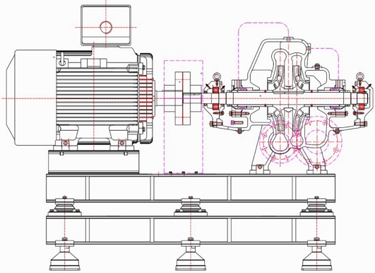
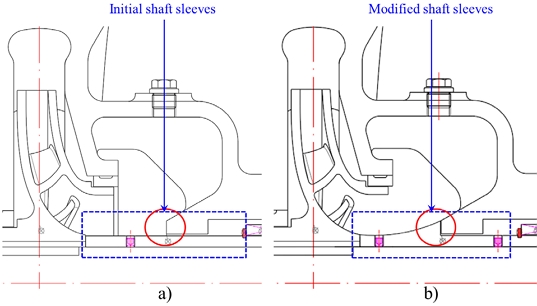
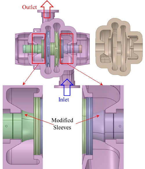
The two-stage centrifugal pump comprises two oppositely arranged impellers with the crossover connector. The schematic view of a two-stage centrifugal pump is shown in Fig. 1. The edge and curve shaft sleeves were used in the two-stage centrifugal pump. The initial and modified shaft sleeves for the two-stage centrifugal pump are shown in Fig. 2. Fig. 3 shows a 3D model of the centrifugal pump and the arrangement of impellers. The magnified view of the modified sleeve is indicated in Fig. 3. The initial shaft sleeve is a conventional design, and the modified shaft sleeve is a curvature design for smooth internal flow. The specific speed NS of the single-stage centrifugal pump is 123.68 [min-1, m3/min, m].
| (1) |
where NS is the specific speed of the pump, N is rotational speed (min-1), H is the effective head (m), Q is the flow rate (m3/min).
2.2 Numerical Methodology
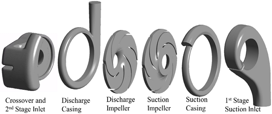
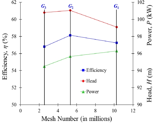
The fluid domain of the two-stage centrifugal pump is shown in Fig. 4. The crossover directs the flow from the suction impeller to the discharge impeller. The numerical grids of the two-stage centrifugal pump are shown in Fig. 5. The numerical grid for the impeller, casing, and clearance gap were generated using ANSYS ICEM 2023R2(19). The unstructured mesh was used for the complex geometry of the two-stage centrifugal pump. The grid dependency test was performed to reduce the influence of grid number on the computational results. CFD analysis is critically dependent on the numerical grids. The mesh dependency test was conducted to obtain the optimal grid numbers for the stable CFD analysis results. Grid convergence test was carried out with grid sizes G1, G2, and G3 using grid convergence index (GCI). The efficiency, head, and power are selected for the sensitivity analysis. GCI is calculated using Eq. (2)(20).
| (2) |
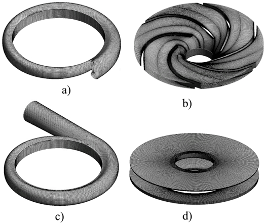
Numerical grids for CFD analysis a) Suction casing, b) Impeller, c) Discharge casing and d) Leakage gap
where G is the grid number, η is efficiency, ϵ is the relative error, r is the grid refinement factor, p0 is the apparent order of numerical solution, the subscript a and ext are approximate and extrapolated relative error values, respectively.
The results of the grid dependency test are shown in Table 1. The grid convergence index is less than 5% for each numerical grid. Fig. 6 shows the grid dependency test of a two-stage centrifugal pump. CFD analysis results are consistent with changes in the numerical grids. 5.4 million nodes are selected for further CFD analysis. CFD analysis was performed for the performance analysis of the two-stage centrifugal pump. ANSYS CFX 2023R2(19) was used for CFD analysis of a two-stage centrifugal pump. The shear stress turbulence model is selected for the numerical calculation because it shows better convergence for the rotating applications than other turbulence models. The inlet and outlet boundary conditions were static pressure and mass flow rate, respectively. The frozen rotor was selected as the interface model between rotating and stationary components. All the boundary walls were smooth with no-slip conditions. Cavitation analysis was conducted using a mixture of water and water vapor with various cavitation numbers. The Rayleigh-Plesset model was used to evaluate the suction performance of a centrifugal pump. The detailed boundary condition for CFD analysis of the two-stage centrifugal pump is shown in Table 2.
Fluid-structure interaction (FSI) is the interdisciplinary branch between fluid and solid mechanics, which discusses the two-way or unidirectional interaction of the fluid with the solid. Kumar et al. showed unilateral FSI analysis to evaluate the structural integrity of the turbomachine impeller(21). In this study, unidirectional coupling was selected for FSI analysis to evaluate the impeller response to the fluid pressure.
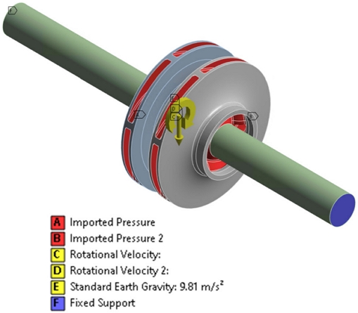
The boundary conditions for the unidirectional FSI are shown in Fig. 7. The unidirectional FSI method takes 3D steady-state numerical simulation to calculate fluid pressure on the blade surface. Then, it loads fluid pressure onto the blade structure to calculate the equivalent stress and deformation distribution and analyze the strength of the impeller. ASTM A743 and ASTM A576 grade steels are used for the impeller and shaft, respectively.
3. Results and Discussion
3.1 Performance curves of two-stage centrifugal pump
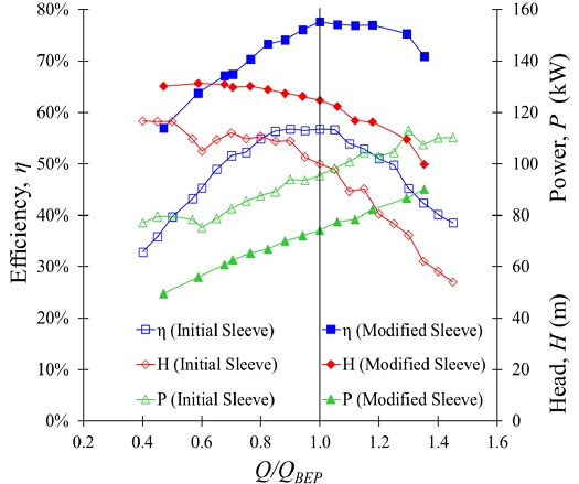
The performance curves of the two-stage centrifugal pump are shown in Fig. 8. The pump efficiency and input power with the initial shaft sleeve are 56% and 96 kW, respectively. It indicates that the performance of two-stage centrifugal pumps is comparatively low. The sleeve modification is the option to improve the pump performance. The efficiency is improved drastically with the modified shaft sleeve than the initial shaft sleeve. The efficiency is increased from 56 to 77% at Q/QBEP=1.00 with the installation of a modified sleeve. The best efficiency is achieved at the design point, which implies that the design of the centrifugal pump is acceptable. An improvement in the pump head and input shaft power is observed with the modified shaft sleeves. The pump head is increased from 98 to 122 m at Q/QBEP=1.00, and shaft input power is decreased from 98 to 77 kW with the installation of a modified shaft sleeve. It indicates that installing a modified shaft sleeve improved the performance of the two-stage centrifugal pump. At Q/QBEP=0.60, the hump region is observed in the two-stage centrifugal pump with the initial sleeve design. The modified shaft sleeve improved the hump region and reduced the shaft power consumption. The modified sleeve improved the effective head, which changed the specific speed of the pump turbine. The specific speeds of two-stage centrifugal pumps with initial and modified sleeves are 123.68 and 111.89, respectively, which are the same type of centrifugal pump impeller.
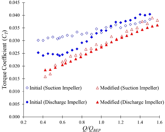
Fig. 9 shows a torque coefficient comparison between the initial and modified sleeves two-stage centrifugal pump. The torque coefficient (CT) is calculated by
| (3) |
where, T is input torque (Nm), ρ is the density of fluid (kg/m3). 𝜔 is rotational speed (rad/s), R is impeller outlet radius (m).
The torque coefficient for the initial sleeve two-stage centrifugal pump is higher than in the modified sleeve. At the Q/QBEP=1.00, the torque coefficient for initial and modified sleeves are 0.034 and 0.028, respectively. The torque coefficient magnitude for initial and modified sleeves in the suction impeller are 0.032 and 0.22, respectively, at Q/QBEP=0.60. It indicates that the power consumption is comparatively lower in the modified sleeve two-stage centrifugal pump than in an initial sleeve.
3.2 Internal flow behavior of two-stage centrifugal pump
The two-stage centrifugal pump performance improvement is observed with the installation of modified shaft sleeves. The comparison of internal flow behavior in the two-stage centrifugal pump with initial and modified shaft sleeves is conducted using CFD analysis. Fig. 10 shows the pressure contours in the cross-section of the two-stage centrifugal pump at Q/QBEP=1.00. At the suction inlet, the static pressure is comparatively lower in the two-stage centrifugal pump with the initial sleeve than in the modified sleeve. The discharge pressure is higher in a two-stage centrifugal pump with a modified sleeve rather than the initial sleeve. It suggests an improvement in the pump head.
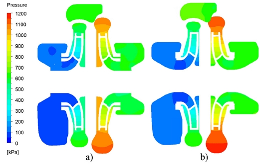
Pressure contours in the two-stage centrifugal pump with a) initial and b) modified sleeves at Q/QBEP=1.00
Fig. 11 shows pressure contours in the suction impeller and casing. The pressure contours comparison indicates that pressure increased drastically with the modified sleeve rather than the initial sleeve. The outlet pressure increased from 500 to 600 kPa in the suction impeller with initial and modified sleeves. Fig. 12 shows the velocity streamlines in a suction impeller at Q/QBEP=1.00. The recirculation and secondary flows are significant in the suction impeller flow passage of a two-stage centrifugal pump with an initial sleeve. The recirculation flow in the suction impeller flow passage causes a pressure drop in the suction impeller.
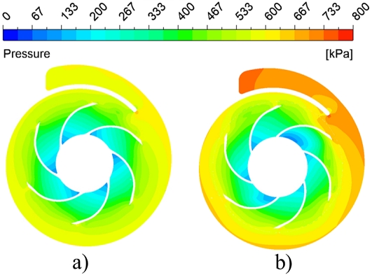
Pressure contours in suction impeller cross-section with a) initial and b) modified sleeves at Q/QBEP=1.00
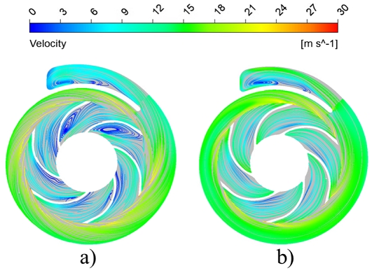
Velocity streamlines in suction impeller cross-section with a) initial and b) modified sleeves at Q/QBEP=1.00
The pressure contours comparison between the initial and modified sleeve in the discharge impeller is shown in Fig. 13. The discharge pressure is comparatively higher in the two-stage centrifugal pump with the modified sleeve than in the initial sleeve. The discharge pressure is improved from 1000 to 1250 kPa with the installation of a modified sleeve. The velocity streamlines in the discharge impeller with initial and modified sleeves are shown in Fig. 14. The secondary flow is visible in the discharge impeller with the initial sleeve rather than the modified sleeve. The flow instabilities are predominant in the suction and discharge impellers with the initial sleeve. The flow improvement in the suction and discharge impellers is observed with the modified sleeve. Hence, the overall performance is improved in the two-stage centrifugal pump with a modified sleeve.
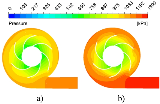
Pressure contours in discharge impeller cross-section with a) initial and b) modified sleeves at Q/QBEP=1.00
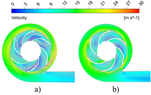
Velocity streamlines in discharge impeller cross-section with a) initial and b) modified sleeves at Q/QBEP=1.00
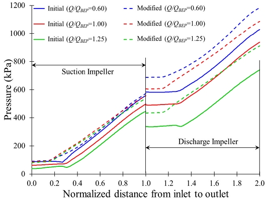
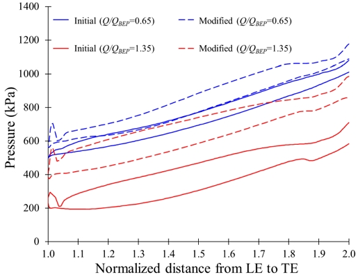
Fig. 15 shows the pressure distribution from inlet to outlet at various flow rates. The magnitude of pressure increases gradually from the inlet to the outlet. The discharge pressure increased by 14%, 15%, and 22% with a modified sleeve at Q/QBEP=0.60, 1.00, and 1.25, respectively. It showed that the modified sleeve design improved the pressure distribution in the centrifugal pump. Fig. 16 indicates the blade loading distribution in the discharge impeller of the two-stage centrifugal pump. The pressure distribution around the blade surface of the modified sleeve impeller is higher than the initial one. At Q/QBEP=0.65 and 1.35, the pressure in the discharge impeller is increased by 8% and 42%, respectively, with a modified sleeve. The modified sleeve improved the static pressure, which decreased the possibility of cavitation in the centrifugal pump.
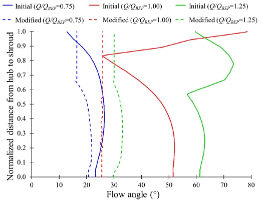
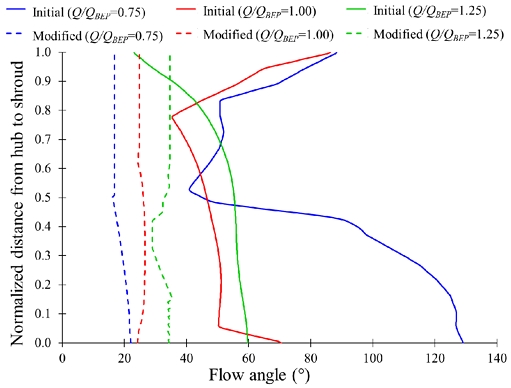
Figs. 17 and 18 show the flow angle comparison at the inlet of suction and discharge impellers with initial and modified shaft sleeves, respectively. The flow angle fluctuation of 10°, 54°, and 18° is observed in the inlet of the suction impeller with the initial sleeve from hub to shroud. With the modified sleeve, the flow angle fluctuation is reduced to 5° in the suction impeller inlet at Q/QBEP=0.75, 1.00, and 1.25. At Q/QBEP=0.75, 1.00, and 1.25, the flow angle is deviated by 36°, 50°, and 88°, respectively, in the inlet of the discharge impeller with an initial sleeve from hub to shroud. At Q/QBEP=0.75, 1.00, and 1.25, the flow angle deviation is less than 6° with the modified sleeve in the discharge impeller inlet. The deviation in the flow angle indicates the fluctuation in the velocity components. The flow angle for the two-stage centrifugal pump with a modified sleeve is consistent compared to the initial sleeve, which improves the velocity streamlines in the impeller flow passage with a modified sleeve.
Figs. 19 and 20 show turbulence kinetic energy (TKE) comparisons at the inlet of suction and discharge impellers, respectively. Turbulence kinetic energy (TKE) calculates turbulence intensity in a fluid flow. The TKE explains the mean kinetic energy per unit masses associated with eddies in turbulent flow and quantifies the fluctuations in velocity caused by eddies and vortices. The TKE is half the sum of the variance of fluctuating velocity components(13).
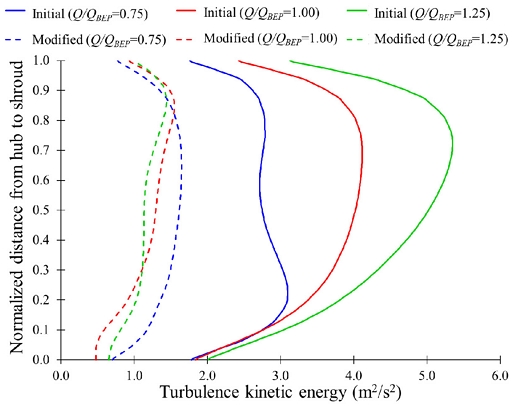
Comparison of turbulence kinetic energy between initial and modified sleeves at suction impeller inlet
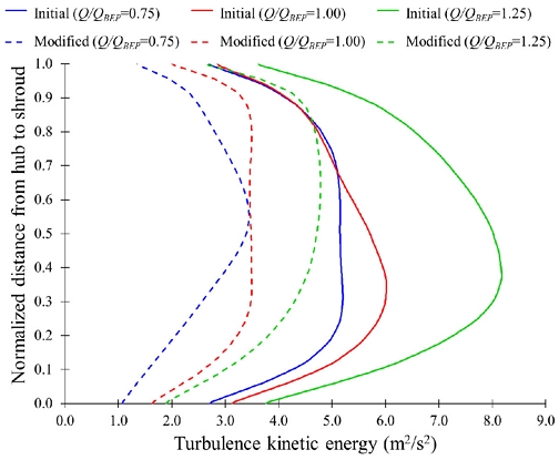
Comparison of turbulence kinetic energy between initial and modified sleeves at discharge impeller inlet
| (4) |
where σu2, σu2, and σu2 are velocity variance in x, y, and z directions, respectively.
TKE intensity at the suction impeller inlet is higher in a two-stage centrifugal pump with an initial sleeve than the modified sleeve. The maximum TKE values in the suction impeller with initial sleeves are 2.41 m2/s2, 4.10 m2/s2, and 5.35 m2/s2 at Q/QBEP=0.75, 1.00 and 1.25, respectively. The maximum TKE values were reduced to 1.65 m2/s2, 1.55 m2/s2, and 1.45 m2/s2 at Q/QBEP=0.75, 1.00, and 1.25, respectively, in the suction impeller inlet with modified sleeve. At Q/QBEP=0.75, 1.00, and 1.25, the intensity of TKE is decreased from 5.16 m2/s2, 6.01 m2/s2, and 8.15 m2/s2 to 3.47 m2/s2, 3.47 m2/s2, and 4.79 m2/s2, respectively with installation of modified sleeve. The TKE intensity is reduced drastically at the inlet of suction and discharge impellers with modified sleeves. Hence, the eddies and vortices quantities are reduced drastically in the suction and discharge impeller flow passage with modified sleeves. The internal flow in the two-stage centrifugal pump became smoother and increased the pump efficiency.
In this study, the two-stage centrifugal pump with an opposed impeller is used to balance the axial thrust in the impeller. The total axial thrust forces FA acting on the impeller and the axial thrust coefficient CF are used to compare the thrust force in the impeller.
| (5) |
where, A (=2πRb) is the impeller exit area (m2), u is impeller peripheral velocity (m/s), R is impeller outlet radius (m), and b is impeller outlet height (m).
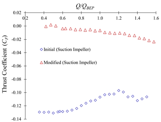
Fig. 21 shows the axial thrust coefficient comparison in the suction impeller. The thrust coefficient magnitude in the initial sleeve is higher than in the modified sleeve. At Q/QBEP=0.40, the thrust coefficient for initial and modified sleeves are –0.1297 and –0.0006, respectively. The negative value indicates that the thrust is exerted from the suction to the discharge sides of the impeller(22). The thrust coefficients in the suction impeller are –0.1064 and –0.0216 for initial and modified sleeves, respectively, at Q/QBEP=1.50. A modified sleeve installation reduces the axial thrust magnitude in the suction impeller.
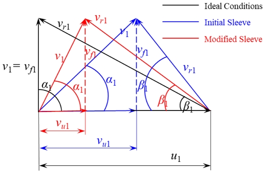
Fig. 22 shows the velocity triangle comparison at the inlet of the suction impeller. At ideal conditions, the flow enters the impeller radially, which implies that α1=90°, vu1=0, and v1=vf1. With a modified sleeve, the tangential velocity (vu1) at the inlet of the suction impeller is lower than the initial sleeve. The modified sleeve reduces the tangential component absolute velocity (v1) and tends to make flow radial. Hence, the modified sleeve installation improves the flow characteristics in the two-stage centrifugal pump.
3.3 Suction performance of two-stage centrifugal pump
The cavitation number is calculated to evaluate the suction performance of the two-stage centrifugal pump with initial and modified sleeves.
| (6) |
where σ is the cavitation number, H is the effective head of the two-stage centrifugal pump, pi is the inlet pressure of the two-stage centrifugal pump, psat is saturated vapor pressure.
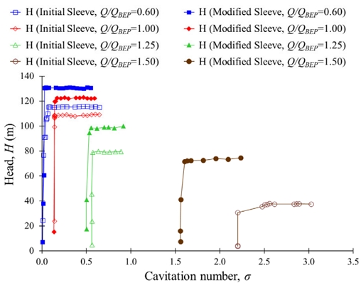
Fig. 23 shows the suction performance of the two-stage centrifugal pump with initial and modified sleeves. The critical cavitation number is high for the higher flow rates. The critical cavitation numbers are 0.04, 0.14, 0.56, and 2.20 for the two-stage centrifugal pump with an initial sleeve at Q/QBEP=0.60, 1.00, 1.25 and 1.50, respectively.
At Q/QBEP=0.60 and 1.00, the critical cavitation number is below 0.5. The possibility of cavitation is comparatively low at the low flow rates. The critical cavitation numbers are 0.02, 0.13, 0.50, and 1.56 at Q/QBEP=0.60, 1.00, 1.25, and 1.50, respectively, in the two-stage centrifugal pumps with modified sleeves. It shows that the critical cavitation number of a two-stage centrifugal pump with a modified sleeve is less than the initial sleeve. At Q/QBEP=1.25, the critical cavitation number and suction heads are 0.56 and 0.50, and 80m and 100m in a two-stage centrifugal pump with initial and modified sleeves, respectively. The suction head is increased from 37m to 73m, and the critical cavitation number decreased from 2.20 to 1.56 at Q/QBEP=1.50 with an installation of the modified sleeve in a two-stage centrifugal pump. Hence, the modified sleeve improved the suction performance of the two-stage centrifugal pump.
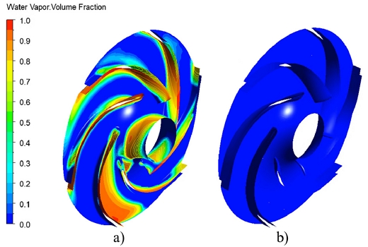
Fig. 24 shows a vapor volume fraction comparison in the impeller of a two-stage centrifugal pump with initial and modified sleeves. The vapor volume fraction legend indicates 0 and 1, which resemble water and water vapor, respectively. At σ=0.56 and Q/QBEP=1.25, the impeller with the initial sleeve succumbed with the vapor volume fraction. Fig. 25 indicates that the impeller with the initial sleeve is susceptible to cavitation. The impeller with the initial sleeve is covered with a larger area of vapor volume fraction at σ=0.56 and Q/QBEP=1.50 than that of the impeller with a modified sleeve. It concludes that the impeller with a modified sleeve shows better suction performance and a low amount of vapor volume fraction.
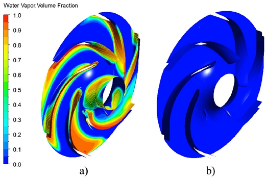
Vapor volume fraction in suction impeller a) initial and b) modified sleeve at Q/QBEP=1.25 and 𝜎=0.56
3.4 Structural analysis of two-stage centrifugal pump
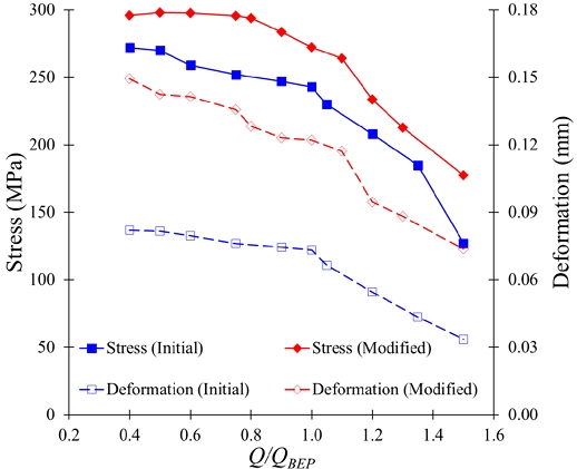
The discharge pressure is above 1000 kPa in a two-stage centrifugal pump with a modified sleeve. The unidirectional FSI analysis i s conducted to perform structural analysis in the two-stage centrifugal pump. Fig. 26 shows equivalent stress and deformation comparison in the two-stage centrifugal pump with initial and modified sleeves. The internal pressure is higher in the two-stage centrifugal pump with a modified sleeve. FSI analysis showed that fluid pressure is directly related to the equivalent stress and deformation. The equivalent stress is increased from 243 to 273 MPa in a two-stage centrifugal pump with an initial and modified sleeve. The deformation is 0.073 to 0.122 mm for a two-stage centrifugal pump with initial and modified sleeves, respectively. Fig. 25 shows that the equivalent stress is below the ultimate tensile stress. It concludes that the two-stage centrifugal pump with a modified sleeve has structural stability.
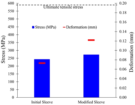
FSI analysis comparison in two-stage centrifugal pump with initial and modified sleeves at Q/QBEP=1.00
Fig. 27 shows the stress and deformation comparison in a two-stage centrifugal pump with initial and modified sleeves. The equivalent stress in the two-stage centrifugal pump is less than the allowable stress with the initial and modified sleeve, which implies that the two-stage pump has structural stability. The deformation in the impeller is less than 0.2mm, which is below the clearance gap. Hence, the two-stage pump is structurally stable with an initial and a modified sleeve.
4. Conclusion
The two-stage centrifugal pump with an opposite impeller arrangement and crossover was designed for industrial purposes. The pump performance curves were evaluated using CFD analysis. The shaft sleeves design changed from edge to curved type. The shaft sleeves modification improved the two-stage centrifugal pump performance and internal flow characteristics. The modified shaft sleeve improved the pump efficiency from 56 to 77% at Q/QBEP=1.00. Besides the pump efficiency, the modified shaft sleeve increased the pump head by 24.5% and decreased shaft input power by 28%. The modified shaft sleeve improved the internal flow behavior in the two-stage centrifugal pump. The modified sleeve reduced the recirculation flow and improved the pressure distribution in the impeller flow passages. A significant improvement in the suction head and vapor volume fraction is observed in the two-stage centrifugal pump with a modified sleeve. In contrast to high internal pressure, the two-stage centrifugal pump with a modified sleeve is structurally stability with equivalent stress and is remarkably below the ultimate tensile stress.
For future works, the parametric design and optimization of the shaft sleeve shape will be carried out to improve performance and internal flow characteristics in the two-stage centrifugal pump.
Acknowledgments
본 과제(결과물)는 2024년도 교육부의 재원으로 한국연구재단의 지원을 받아 수행된 지자체-대학 협력기반 지역혁신사업의 결과입니다(재단과제관리번호: 광주전남플랫폼 2021RIS-002).
References
- Kalaiselvan, A. S., V, Subramaniam, U., Shanmugam, P. and Hanigovszki, N., 2016, “A comprehensive review on energy efficiency enhancement initiatives in centrifugal pumping system,” Applied Energy, Vol. 181, pp. 495-513.
- Mckee, K. K., Forbes, G., Mazhar, I., Entwistle, R. and Howard, I., 2011, “A review of major centrifugal pump failure modes with application to the water supply and sewerage industries.” in ICOMS Asset Management Conference, Australia.
- Shojaeefard, M. H., Salimian Rizi, B., Khalkhali, A. and Tahani, M., 2015, “A new method to calculate centrifugal pump performance parameters for industrial oils,” Journal of Applied Fluid Mechanics, Vol. 8, No. 4, pp. 673-681.
- Marathe, S. P., Saxena, R. R., and Solanki, C. H., 2013, “Numerical analysis on the performance characteristics of the centrifugal pump,” International Journal of Engineering Research and Application, Vol. 3, No. 3, pp. 1466-1469.
- Cui, B. and Li, C., 2023, “Influence of Axial Matching between Inducer and Impeller on Energy Loss in High-Speed Centrifugal Pump,” Journal of Marine Science and Engineering, Vol. 11, No. 5, pp. 940.
- Kim, H. I., Roh, T. S., Huh, H. and Lee, H. J., 2022, “Development of ultra-Low specific speed centrifugal pumps design method for small liquid rocket engines,” Aerospace, Vol. 9, No. 9, pp. 477.
- Zhang, J., Li, G., Mao, J., Yuan, S., Qu, Y. and Jia, J., 2018, “Effects of the outlet position of splitter blade on the flow characteristics in low-specific-speed centrifugal pump,” Advances in Mechanical Engineering, Vol. 10, No. 7, pp. 1-12.
- Onari, M. M. and Arzani, V. G., 2014, “Repetitive shaft crack failure analysis on a multistage centrifugal pump in reactor charge service in a nuclear power plant-based on ODS and FEA,” in 43rd Turbomachinery & 30th Pump Users Symposia, Houston.
- Coutier-Delogsha, O., Fortes-Patella, R., Reboud, J. L., Hofmann, M. and Stoffel, B., 2003, “Experimental and numerical and studies in a centrifugal pump with two-dimensional curved blades in cavitating condition,” Journal of Fluid Engineering, Vol. 125, pp. 970-978.
- Bakir, F., Rey, R., Gerber, A. G., Belamri, T. and Hutchinson, B., 2004, “Numerical and experimental investigations of the cavitating behavior of an inducer,” International Journal of Rotating Machinery, Vol. 10, pp. 15-25.
- Lu, Y., Tan, L., Zhao, X. and Ma, C., 2024, “Experiment on cavitation-vibration correlation of a centrifugal pump under steady state and start-up conditions in energy storage station,” Journal of Energy Storage, Vol. 83, pp. 110763.
- Zhao, X. A., Huang, B., Chen, T., Wang, G., Gao, D. and Zhao, J., 2017, “Numerical simulations and surrogate-based optimization of cavitation performance for an aviation fuel pump,” Journal of Mechanical Science and Technology, Vol. 31, No. 2, pp. 705-716.
- Chen, B., Chen, H., Li, X. and Zhu, Z., 2024, “Research on the effects of different blade leading-edge geometries on the internal and external characteristics of centrifugal pumps,” Ocean Engineering, Vol. 309, pp. 118371.
- Sakran, H. K., Aziz, A., Sharizal, M. and Khor, C. Y., 2024, “Blade Wrap Angle Impact on Centrifugal Pump Performance: Entropy Generation and Fluid-Structure Interaction Analysis,” CMES-Computer Modeling in Engineering & Sciences, Vol. 140, No. 1, pp. 109-137.
- Chen, J., Shi, W. and Zhang, D., 2021, “Influence of blade inlet angle on the performance of a single blade centrifugal pump,” Engineering Applications of Computational Fluid Mechanics, Vol. 15, No. 1, pp. 462-475.
- Wu, T., Wu, D., Gao, S., Song, Y., Ren, Y. and Mou, J., 2023, “Multi-objective optimization and loss analysis of multistage centrifugal pumps,” Energy, Vol. 284, pp. 128638.
- Zhao, J., Pei, J., Yuan, J. and Wang, W., 2023, “Structural optimization of multistage centrifugal pump via computational fluid dynamics and machine learning method,” Journal of Computational Design and Engineering, Vol. 10, No. 3, pp. 1204-1218.
- Saruhan, H. and Kam, M., 2016, “Experimental spectral analysis of split sleeve bearing clearance effect on a rotating shaft system,” Electronic Journal of Machine Technologies, Vol. 13, No. 4, pp. 1-8.
- ANSYS Inc., 2023, “ANSYS CFX documentation ver 2023R2”, http://www.ansys.com, .
- Celik, I. B., Ghia, U., Roache, P. J., Freitas, C. J., Coleman, H. and Raad, P. E., 2008, “Procedure for Estimation and Reporting of Uncertainty Due to Discretization in CFD Applications,” Journal of Fluids Engineering, Vol. 130, No. 7, pp. 078001.
- Kumar, M., Venkateshwaran, A., Kumar, M. S. S. P., Sreekanth, M., Jebaseelan, D. and Sivakumar, R., 2022, “Strength analysis of a regenerative flow compressor and a pump based on fluid-structure coupling,” Materials Today: Proceedings, Vol. 51, pp. 1619-1624.
- Yamashita, T., Watanabe, S., Hara, Y., Watanabe, H. and Miyagawa, K., 2015, “Measurements of axial and radial thrust forces working on a three-stages centrifugal pump rotor,” In Fluids Engineering Division Summer Meeting, American Society of Mechanical Engineers, Vol. 57213, p. V01AT33A013.
