CFD Analysis on the Internal Flow of Swirling Ultrafine Bubble Generator for CO2 Gas Dissolution
Abstract
In recent times, the application of fine bubbles has increased rapidly. Bubbles in the liquid are classified according to their diameter. The bubbles size from 1 μm to 100 μm are called microbubbles, which rise at a slower rate and cause rapid dissolution. The ultrafine bubbles are the bubble size less than 1 μm, which will not rise and stay in a liquid medium for a long time. Fine bubbles are applied in aquaculture, agriculture, clinical medicine, food, and chemical industry. Ultrafine bubble generation is difficult, but numerous methods like swirling liquid, venturi, ejector, pressurized, dissolution, and electrolytic types are available to generate ultra-fine bubbles. The swirling flow generator with a regenerative pump is selected to generate ultrafine bubbles. CO2 gas and water pass through the regenerative pump and enter the swirling flow generator that generates ultrafine bubbles. When the inlet velocity of CO2 is lower, the size of the bubble diameter decreases. The cylinder, divergent, and convergent conical shape swirling flow generators are designed to reduce the bubble size distribution. The conical shape swirling flow generator reduces the fine bubble to less than 50 μm.
Keywords:
Ultrafine bubble, Bubble generator, CO2 gas, Dissolution, Regenerative pump키워드:
초미세기포, 기포 발생장치, CO2 기체, 용해, 재생형 펌프1. Introduction
Recently, industrial and consumer applications of fine bubbles have been increasing rapidly. Fine bubbles are used for the cleaning effect, water purification(1,2), aquaculture, control of chemical reactions(3), quality control of food(4), and mineral flotation(5). The fine bubbles are bubbles with a diameter of less than 100 μm. The fine bubble with a diameter of more than 1μm is a microbubble, and less than 1μm is an ultrafine bubble(6). The non-fine bubbles are spherical and rise and burst at the water surface. Microbubbles rise slower than non-fine bubbles, whereas ultrafine bubbles no longer rise and stay in water for a long time.
The bubble size and distribution significantly affect heat and mass transfer between the gas and liquid phases. Several typical ultrafine bubble generators based on hydrodynamics have developed over the past decades, such as pressurized dissolution-type(7), spiral liquid flow-type(8), venturi-type(9), and ejector-type(10).
Among them, the most widely used is shearing and breaking gas into microbubbles through turbulence induced by flowing liquid, such as swirling-type, jet-type, and venturi-type ultrafine bubble generators. A swirl flow field was introduced to strengthen the turbulence level of flowing liquid and further enhance the shear breakage effect of bubbles. In this regard, various swirl-type ultrafine bubble generators, which utilize the shear force induced by the vortex breakdown to produce fine bubbles, have been designed and developed in recent years, including tangential swirl-type and axial swirl-type. Ding et al.(11) designed an axial swirl-type microbubble generator by installing a new bubble-breaking mechanism to promote bubble breakup.
In this study, the water and CO2 two-phase flow numerical simulation was performed to investigate the generation of ultrafine bubbles of CO2 gas. The various types of swirling flow generators are used to generate the ultrafine bubble of CO2 gas. The comparative study of the various ultrafine bubble generators is accomplished in this study.
2. Modeling and Methodology
2.1 Modeling of swirling type bubble generator
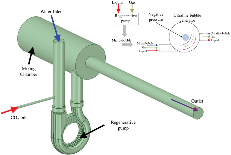
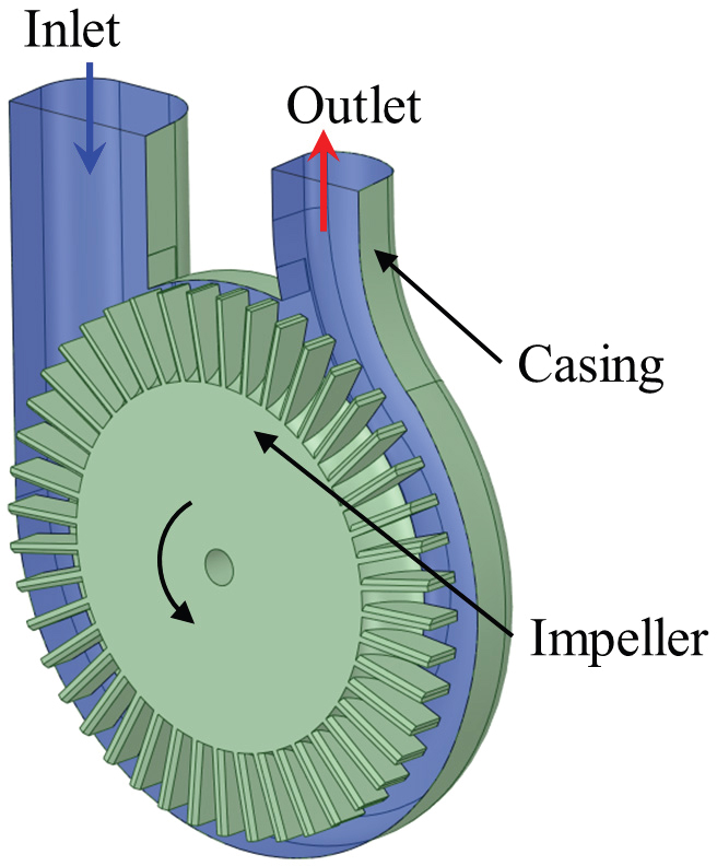
Fig. 1 shows the design and modeling of an ultrafine bubble generator with a regenerative pump. The water and CO2 are the intakes for the ultrafine bubble generator. The mixing of water and CO2 takes place in the regenerative pump and mixing chamber. The swirling motion of the mixture initiates the formation of the fine bubbles. The strength of the swirling motion determines the diameter of fine bubbles. Fig. 2 indicates the cross-section view of the regenerative pump with the impeller blade and casing flow passage. The design of the regenerative pump is adopted from the previous study(12). The regenerative pump increases the pressure from the inlet to the outlet. Fig. 3 is the schematic view of a swirling liquid flow type ultrafine bubble generator. The swirling liquid flow type is widely used for microbubble generators. The swirling motion and shear flow of the water and CO2 in the regenerative pump and mixing chamber generate micro and ultrafine bubbles.
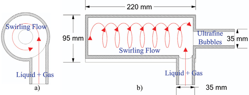
Ultrafine bubble generator using swirling flow generation method a) radial and b) side cross-section view(6)
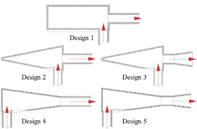
Fig. 4 shows the various designs of swirling flow generators used to produce ultrafine bubbles. The five types of swirling flow generators are shown in Fig. 4. Design 1 is cylindrical with a simple inlet and outlet. Designs 2 and 3 used the divergent conical with simple and divergent outlet pipes for the swirling flow generator, respectively. The convergent conical with simple and divergent outlet pipes are used for designs 4 and 5, respectively.
2.2 Numerical methodology
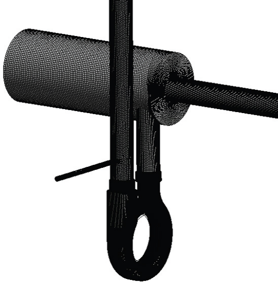
The computational fluid dynamics code of ANSYS CFX 2022R2(13) is employed to investigate the swirling flow generator performance and internal flow behavior. Fig. 5 shows the numerical grids for the numerical analysis. ANSYS ICEM 2022R2(13) generated the hexahedral numerical grids of the regenerative pump and mixing chamber. The y+ values for the numerical grids are less than 100.
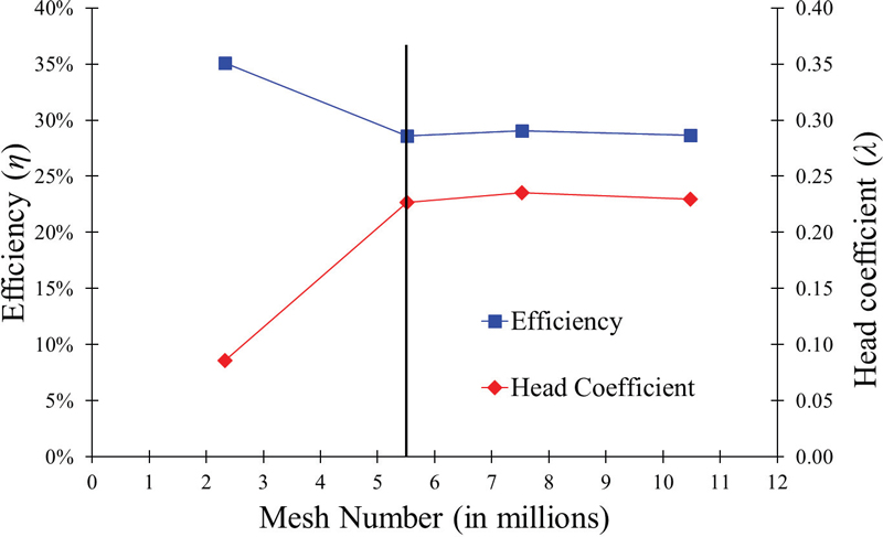
Fig. 6 shows the mesh dependency test and the optimum number for CFD analysis. According to the mesh dependency test, a 5.5million node number is suitable for the stable CFD analysis. The further increase in the mesh number does not influence the CFD analysis results.
The mixture of water and CO2 is considered for steady-state CFD analysis. The continuous phase is water with a density of 997kg/m3 and viscosity of 0.89×10⁻³kg/m.s. CO2 is used as polydispersed fluid with a density of 1.977kg/m3 and viscosity of 1.49×10⁻⁵kg/m.s to simulate the bubble formation in the swirling flow generator. The multiphase Reynolds Navier-Stokes equations, combined with the shear stress transport (SST) turbulence model, were selected to analyze the bubble flow in the mixing chamber. The homogeneous multiple-size group (MUSIG) was employed to evaluate the bubble size(14,15). Luo bubble breakup model(16) and the Prince bubble coalescence model(17) are selected.
CFD analysis uses a static pressure condition for the water inlet, a velocity inlet for CO₂, and a mass flow rate condition for the mixture outlet. Table 1 provides the detailed boundary conditions for the CFD analysis of the ultrafine bubble generator.
The numerical analysis is performed with various CO2 inlet velocities of 2m/s, 3m/s, and 4m/s for each design type.
3. Results and Discussion
3.1 Performance curves of regenerative pump
The dimensionless terms were used to evaluate the performance of regenerative pumps(18).
| (1) |
| (2) |
| (3) |
where, λ is head coefficient, ϕ is flow coefficient, ω is rotational speed (rad/s), D is impeller outer diameter (m), ρ is density of fluid (kg/m3), g is acceleration due to gravity (m/s2), Q is flow rate (m3/s), H is effective head (m), τ is torque consumed by impeller (Nm).
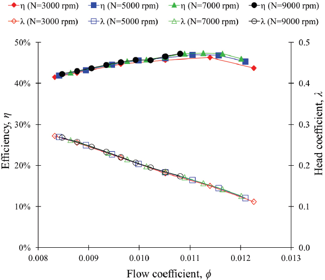
Fig. 7 illustrates the performance curves of the regenerative pump with a straight impeller blade. The efficiency and the head coefficient of the regenerative pump are 47.4 % and 0.157 at ϕ=0.0113. The efficiency and the head coefficient of the regenerative pump are constant with rotational speed variation, and the similarity law of the performance matches well. The design and CFD analysis of the regenerative pump are satisfied(19).
3.2 Effect of CO2 inlet velocity in the swirling type ultrafine bubble generator
The bubble generation in the mixing chamber is dependent on the various parameters. The influence of CO2 inlet velocity is considered for the ultrafine bubble generation. In this study, the CO2 inlet velocities of 2m/s, 3m/s, and 4m/s were considered to maintain the sufficient mass flow rate of CO2 gas. Fig. 8 shows the influence of CO2 inlet velocity on the bubble mean diameter distribution. The inlet CO2 velocity showed the variation of bubble mean diameter distribution in the swirling flow generator. The maximum bubble mean diameter is 200 μm, 126μm, and 60μm for CO2 inlet velocity 4m/s, 3m/s, and 2m/s, respectively. The results indicate that a lower CO2 inlet velocity is more effective for generating smaller bubbles.
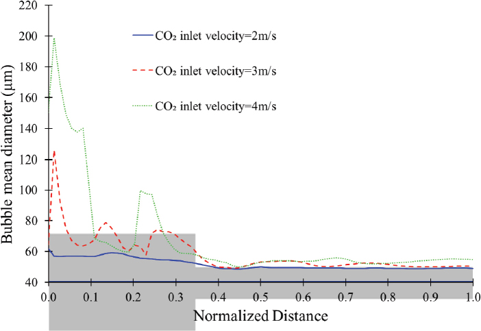
Bubble diameter size distribution in swirling flow generator design 1 according to CO2 inlet velocity
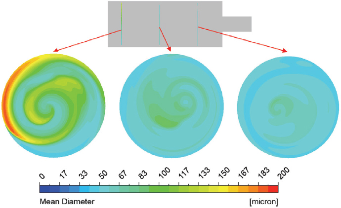
Fig. 9 presents a cross-sectional view of bubble mean diameter contours in the mixing chamber of swirling flow generator design 1. Fig. 9 indicates that the bubble’s mean diameter decreases as the flow moves toward the outlet. It implies that the swirling flow generator design is suitable for ultrafine bubble generation.
3.3 Effect of swirling flow generator designs on ultrafine bubble generation
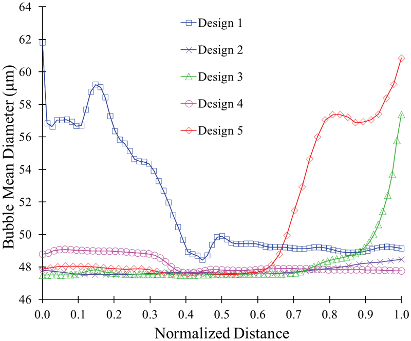
A comparative study of the various swirling flow generator design shapes was performed. The bubble mean diameter distribution in the swirling flow generator is shown in Fig. 10. The bubble mean diameter increases suddenly at the outlet pipe for swirling flow generator designs 3 and 5. It suggests that the divergent outlet pipe drastically increases the mean bubble diameter.
The mean bubble diameter is less than 50μm for swirling flow generator designs 2 and 4. Therefore, it concludes that a conical-shaped swirling flow generator with a simple outlet pipe is preferable for ultrafine bubble generation.
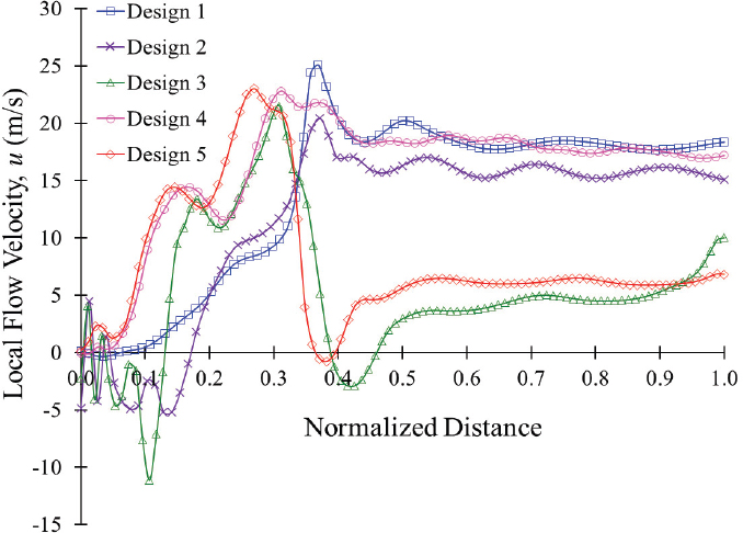
Fig. 11 shows the flow velocity distribution in the swirling flow generator. The flow velocities for designs 1, 2, and 4 are relatively higher than for designs 3 and 5. The flow velocity maintains the turbulence and swirling flow in the ultrafine bubble generator. Designs 2 and 3 showed negative flow velocity, which indicates that reverse flow in the chamber reduces the secondary vortex intensity in the ultrafine bubble generator. Designs 3 and 5 have divergent diffuser outlet pipes, which reduces the flow velocity and swirling strength in the ultrafine bubble generator. It suggests that a convergent conical diffuser with a simple outlet pipe effectively maintains high flow velocity and secondary flow in the ultrafine bubble generator.
Fig. 12 shows the secondary vortex intensity distribution in the swirling flow generator. The secondary vortex intensity quantifies the occurrence of secondary flow in the ultrafine bubble generator. The secondary vortex intensity is defined as the absolute vorticity flux in the normal direction of the cross-section area(20).
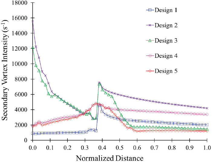
Secondary vortex intensity distribution in the swirling flow generator with 2 m/s CO2 inlet velocity
| (4) |
where Ju is the secondary vortex intensity, u is the local flow velocity.
The secondary vortex intensity distribution is dependent on the swirling flow generator design. The swirling flow generator design 1 showed the minimum secondary vortex intensity. It implies that the lower secondary vortex intensity increases the bubble diameter. The divergent and convergent conical shape swirling flow generator showed the decreasing and increasing tendency of secondary vortex intensity. At the outlet, the secondary vortex intensity is comparatively lower for swirling flow generator designs 3 and 5, which increases the bubble mean diameter. The secondary vortex intensities for designs 2 and 4 are higher, which decreases the mean bubble diameter. Hence, the swirling flow generator designs 2 and 4 can be considered for ultrafine bubble generation.
Fig. 13 shows the turbulence kinetic energy and pressure comparison between swirling flow generator designs 1 and 4. The turbulence kinetic energy (TKE) is produced by fluid shear, friction, and buoyancy. It is calculated from the root mean square of the turbulent fluid velocities fluctuations in x, y, and z directions.
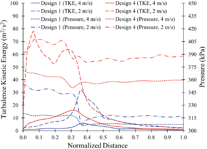
Comparison of turbulence kinetic energy and pressure between swirling flow generator design 1 and design 4 with various CO2 inlet velocity
| (5) |
where , , and are velocities variance in x, y, and z directions, respectively.
The TKE is directly related to the turbulence flow in the swirling flow generator. The TKE plays a vital role in breaking up and reducing bubble size(21). The TKE is higher for design 4, which effectively breaks and reduces the bubble size compared to design 1. The higher value of TKE contributes to maintaining the swirling flow in the ultrafine bubble generator. In designs 1 and 4 with 4m/s CO2 inlet velocity, the pressure decreases from 320kPa to 306kPa and 371kPa to 350kPa, respectively. The pressure drop in the ultrafine bubble generator is directly related to the increase in TKE. The TKE value increases from 6m2/s2 to 32m2/s2 and 18m2/s2 to 78m2/s2 for designs 1 and 4 with an decrease in CO2 inlet velocity from 4m/s to 2m/s, respectively.
Figs. 14 and 15 show the comparison of bubble diameter in the various locations of vertical lines in the cross-sectional planes of the swirling flow generator with designs 1 and 4 with 4m/s and 2m/s CO2 inlet velocity, respectively. The bubble diameter is more than 100 μm for design 1, but the bubble diameter is lower than 50μm for design 4 with 4m/s CO2 inlet velocity. The decrease in the CO2 inlet velocity from 4m/s to 2m/s decreases the bubble mean diameter in designs 1 and 4. It suggests that design 4 is preferable to generate an ultrafine bubble with different inlet CO2 velocities.
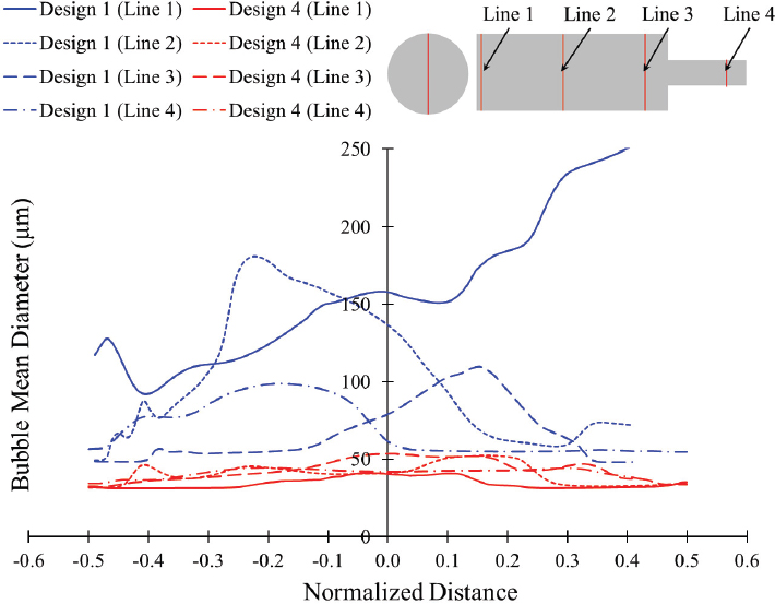
Comparison of bubble mean diameter between swirling flow generator design 1 and design 4 with 4m/s CO2 inlet velocity
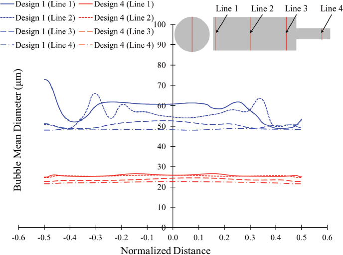
Comparison of bubble mean diameter between swirling flow generator design 1 and design 4 with 2m/s CO2 inlet velocity
Figs. 16 and 17 show the bubble mean diameter contours in swirling flow generator designs 1 and 4 with a CO2 inlet velocity of 4m/s and 2m/s, respectively. Design 4 shows the bubble diameter of less than 50μm and 25μm throughout the ultrafine bubble generator with CO2 inlet velocity of 4m/s and 2m/s, respectively.
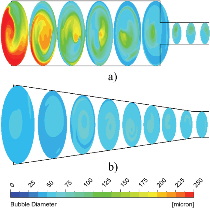
Bubble diameter contours between swirling flow generator a) design 1 and b) design 4 with 4m/s CO2 inlet velocity
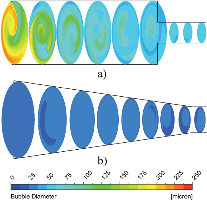
Bubble diameter contours between swirling flow generator a) design 1 and b) design 4 with 2 m/s CO2 inlet velocity
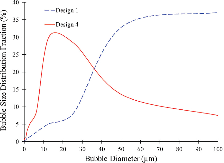
Fig. 18 illustrates the bubble size distribution for swirling flow generator designs 1 and 4. Design 1 primarily generates bubbles with a mean diameter exceeding 50μm. Design 4 predominantly produces bubbles with a mean diameter below 20μm. Notably, 10 % of the bubbles produced by design 4 are smaller than 10μm, indicating its capability to generate ultrafine bubbles.
4. Conclusion
The generation of ultrafine bubbles with a regenerative pump and swirling flow generator was performed, and the water-CO2 two-phase modeling was applied with the CFD-MUSIG model. The CFD analysis showed the flow simulation and bubble size distribution in the swirling flow generator. The cylindrical and conical-shaped swirling flow generators were used to generate ultrafine bubbles. In addition, outlet pipe shape was investigated to improve ultrafine bubble size.
The water and CO2 are entered separately in the regenerative pump, which mixes water and CO2. The mixture of water and CO2 passes into a swirling flow generator and produces ultrafine bubbles. The divergent outlet pipe in swirling flow generator designs 3 and 5 increases the bubble mean diameter from 47μm to 57μm and 61μm when the inlet CO2 velocity is 2m/s, respectively. The swirling flow generator designs 2 and 4 generated ultrafine bubbles with a diameter of less than 50μm through the swirling flow generator. Design 4 shows a higher turbulence kinetic energy than design 1, which maintains swirling flow and reduces the bubble diameter. Furthermore, the bubble diameter is decreased below 10μm in ultrafine bubble generator design 4 with 2m/s CO2 inlet velocity. Hence, the swirling flow generator design 4 is more suitable and efficient for ultrafine bubble generation.
As the purpose of this study is to produce the ultrafine bubble, in the future, inlet CO2 velocity variation, a serial combination of muti-stage ultrafine bubble generator, and the shape optimization process of the ultrafine bubble generator will be performed in the swirling flow generator to generate a bubble diameter of less than 1μm.
Acknowledgments
본 과제(결과물)는 2024년도 교육부의 재원으로 한국연구재단의 지원을 받아 수행된 지자체-대학 협력기반 지역혁신사업의 결과입니다. (재단 과제관리번호 : 광주전남플랫폼 2021RIS-002)
References
-
Shankar, V. K. A., Umashankar, S., Paramasivam, S. and Hanigovszki, N., 2016, “A comprehensive review on energy efficiency enhancement initiatives in centrifugal pumping system,” Applied Energy, Vol. 181, pp. 495-513.
[https://doi.org/10.1016/j.apenergy.2016.08.070]

-
Khuntia, S., Majumder, S. K. and Ghosh, P., 2012, “Microbubble-aided water and wastewater purification: a review,” Reviews in Chemical Engineering, Vol. 28, pp. 191-221.
[https://doi.org/10.1515/revce-2012-0007]

-
Dai, J., Yu, C., Ye, S., Li, W., Kang, X., Yang, Y. and Yang, Y., 2021, “The intermittent dormancy of ethylene polymerization with the assistance of nitrogen microbubbles,” Macromolecules, Vol. 54, No. 20, pp. 9418-9426.
[https://doi.org/10.1021/acs.macromol.1c01274]

-
Xu, Q., Nakajima, M., Ichikawa, S., Nakamura, N. and Shiina, T., 2008, “A comparative study of microbubble generation by mechanical agitation and sonication,” Innovative food science and emerging technologies, Vol. 9, No. 4, pp. 489-494.
[https://doi.org/10.1016/j.ifset.2008.03.003]

-
Cho, Y. S. and Laskowski, J. S., 2002, “Effect of flotation frothers on bubble size and foam stability,” International Journal of Mineral Processing, Vol. 64, pp. 69-80.
[https://doi.org/10.1016/S0301-7516(01)00064-3]

-
Terasaka, K., Yasui, K., Kanematsu, W. and Aya, N., 2021, Ultrafine bubbles. CRC Press.
[https://doi.org/10.1201/9781003141952]

-
Maeda, Y., Hosokawa, S., Baba, Y., Tomiyama, A. and Ito, Y., 2015, “Generation mechanism of micro-bubbles in a pressurized dissolution method,” Experimental Thermal and Fluid Science, Vol. 60, pp. 201-207.
[https://doi.org/10.1016/j.expthermflusci.2014.09.010]

-
Li, P. and Tsuge, H., 2006, “Water treatment by induced air flotation using microbubbles,” Journal of chemical engineering of Japan, Vol. 39, No. 8, pp. 896-903.
[https://doi.org/10.1252/jcej.39.896]

-
Wu, M., Yuan, S., Song, H. and Li, X., 2022, “Micro-nano bubbles production using a swirling-type venturi bubble generator,” Chemical Engineering and Processing-Process Intensification, Vol. 170, pp. 108697.
[https://doi.org/10.1016/j.cep.2021.108697]

-
Shuai, Y., Wang, X., Huang, Z., Yang, Y., Sun, J., Wang, J. and Yang, Y., 2019, “Bubble size distribution and rise velocity in a jet bubbling reactor,” Industrial and Engineering Chemistry Research, Vol. 58, No. 41, pp. 19271-19279.
[https://doi.org/10.1021/acs.iecr.9b03880]

- Ding, G., Chen, J., Wang, C., Shao, C., Liu, M., Cai, X. and Ji, Y., 2018, “Structural design and numerical simulation of axial-swirling type micro-bubble generator,” Chinese Journal of Process Engineering, Vol. 18, No. 5, pp. 934-941.
-
Shrestha, U., Kim, P. and Choi, Y-D., 2023, “Effects of Impeller Blade Shape and Impeller Disk Side Gap Passage Shape on the Regenerative Blower Performance,” The KSFM Journal of Fluid Machinery, Vol. 26, No. 5, pp. 79-88.
[https://doi.org/10.5293/kfma.2023.26.5.079]

- ANSYS, ANSYS CFX Documentation, 2021, ANSYS. Inc, Pennsylvania.
-
Krepper, E., Lucas, D., Frank, T., Prasser, H. M. and Zwart, P. J., 2008, “The inhomogeneous MUSIG model for the simulation of polydispersed flows,” Nuclear Engineering and Design, Vol. 238, No. 7, pp. 1690-1702.
[https://doi.org/10.1016/j.nucengdes.2008.01.004]

-
Lee, J. W., Jung, K. J. and Kim, Y. J., 2020, “Numerical analysis on performance of induced gas flotation machine using MUSIG model,” Engineering Applications of Computational Fluid Mechanics, Vol. 14, No. 1, pp. 778-789.
[https://doi.org/10.1080/19942060.2020.1771426]

-
Luo, H. and Svendsen, H. F., 1996, “Theoretical model for drop and bubble breakup in turbulent dispersions,” AIChE Journal, Vol. 42, No. 5, pp. 1225-1233.
[https://doi.org/10.1002/aic.690420505]

-
Prince, M. J. and Blanch, H. W., 1990, “Bubble coalescence and break‐up in air‐sparged bubble columns,” AIChE Journal, Vol. 36, No. 10, pp. 1485-1499.
[https://doi.org/10.1002/aic.690361004]

-
Hollenberg, J. W. and Potter, J. H., 1979, “An investigation of regenerative blowers and pumps”.
[https://doi.org/10.1115/1.3439487]

- Quail, F. J., 2009, “Design study of a regenerative pump using numerical and experimental techniques,” Thesis, University of Strathclyde, Glasgow.
-
Shrestha, U. and Choi, Y-D, 2021, “Suppression of flow instability in the Francis hydro turbine draft tube by J-groove shape optimization at a partial flow rate.,” Journal of Mechanical Science and Technology, Vol. 35, No. 6, pp. 2523-2533.
[https://doi.org/10.1007/s12206-021-0523-2]

-
Amini, E., Bradshaw, D. J., Finch, J. A. and Brennan, M., 2013, “Influence of turbulence kinetic energy on bubble size in different scale flotation cells.,” Minerals Engineering, Vol. 45, pp. 146-150.
[https://doi.org/10.1016/j.mineng.2013.01.015]

