A Numerical Study on the Effects of Liquid Hydrogen Tank Sloshing Parameters and Rib Structure on the Tank Internal Flow
Abstract
Sloshing occurs in the partially filled tank under external acceleration. The sloshing dynamics in the liquid hydrogen tank are influenced by the frequency and amplitude of loading conditions, hydrogen filling level, the geometry of the tank, and wave motion. The 30 %, 50 %, and 90 % hydrogen filling levels are selected to evaluate the sloshing dynamics. The pure surge motion is exerted to visualize the free surface movement. Finally, the rib structure is applied in the liquid hydrogen tank to reduce sloshing dynamics. Rib structures of various lengths are employed in the tank to minimize violent oscillation. The long rib structure is more effective in preventing violent free surface fluctuation than the shorter one. Furthermore, FSI analysis showed that the liquid hydrogen tank is structurally safe even with the addition of a rib structure.
Keywords:
Sloshing, Liquid hydrogen tank, Filling level, FSI analysis, Rib Structure키워드:
슬로싱, 액체수소 탱크, 충전레벨, 유체-구조 연성해석, 리브구조1. Introduction
Sloshing is a violent and complex motion phenomenon between two or more fluids in a closed vessel. Liquid sloshing occurs in the transportation system, especially ocean transportation, large crude carriers, liquefied petroleum gas (LPG), liquefied natural gas (LNG), and liquid hydrogen(1). The sloshing motion arises due to various factors, such as the frequency and amplitude of load conditions, the natural frequency of the tank, the geometry of the tank, and filling levels(2). Sloshing can exert fluid pressures and impact load in the transportation tanks, which might cause joint failure and compromise the structural integrity(3). Sloshing affects motion stability and causes disastrous accidents for liquid cargo ships(4).
The sloshing motion can be solved using numerical analysis. It can be achieved by potential flow theory and the viscous Navier-Stokes equation. The non-linear wave potential theory was applied to analyze the 3D tank(5). The potential flow theory predicts the 3D sloshing response in a rectangular LNG tank under force excitation and artificial damping model(6). Navier strokes and free surface equations are applied to evaluate the sloshing dynamics in the rectangular road container(7). A finite-element model was applied to encounter the effect of fluid properties and tank flexibility on the coupled sloshing analysis(8). The boundary element method is used to understand the non-linear sloshing dynamics for pure sway and three degrees of freedom motions(9). Khezzar et al. compared the sloshing dynamics with the volume of fluid method(10). Salem concluded that the partially filled tanker with trammel pendulums reduces the sloshing excitation frequency(11). Liu and Lin studied the effect of horizontal and vertical baffles on the suppression of sloshing dynamics. They concluded that the vertical baffle is more effective than the horizontal baffle in suppressing the impact of sloshing dynamics(12). Multiple vertical baffles mitigate the sloshing force more effectively than a single one(13). The high excitation amplitude increased the pressure response in both unbaffled and baffled cases(14). The baffle’s width shows less significance in suppressing the sloshing wave and amplitude in the partially filled tank under seismic and vertical excitation(15). The vertical baffles are effective for lower filling levels and cases where the baffle is located close to the free surface(16). Single and double vertical baffles of different heights were installed in the tank to suppress the amplitude of the sloshing wave(17). The non-linear baffle shapes were superior in suppressing sloshing pressure than traditional straight baffle shapes(18). Lei et al. optimized the T-shape baffle to reduce the fluid movement in the tank(19).
Sloshing can create dynamic pressure on the tank wall. This dynamic pressure has an impact on the structural stability of the tank. Fluid-structure interaction helps to understand the sloshing dynamics’ impact. The sloshing dynamic for liquid hydrogen is studied with liquid hydrogen level, wave amplitude, and wave movement. The rib structure is installed in the tank to prevent violent free surface movement. The various lengths were used to evaluate the influence of rib structure on suppressing violent oscillation in the liquid hydrogen tank.
2. Design and Numerical Methodology
2.1 Tank Geometry Model
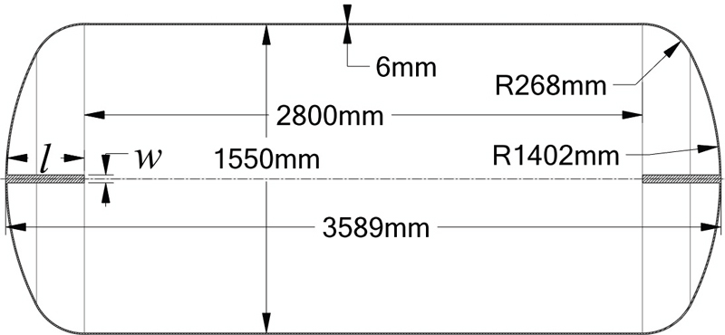
A liquid hydrogen tank is designed based on the design of cryogenic vessels. The minimum wall thickness must be 3mm and 4mm when the vessel diameter is less and more than 1800mm, respectively(20). While designing the pressure vessel, the minimum shell thickness must be 4.76mm(21). Fig. 1 shows the schematic view of the tank geometry. The cylindrical tank shape is selected because it is cheap and easy to manufacture with high packing efficiency for storage and transportation(22).
The diameter and length of the tank are 1550mm and 3589mm, respectively. Considering the safety factor, a 6mm wall thickness is selected.
Fig. 1 shows the installation of the rib structure in the sloshing tank. The main design parameters of rib structure are length (l) and width (w). The various rib structures were selected for the parametric study. The increase in the length and width of the rib structure can cause structural instability in the sloshing tank. The constant width (w) of 40mm is selected to withstand the sloshing dynamic pressure and the cost-effective manufacturing with lengths (l) of 75mm, 250mm, and 400mm.
2.2 Numerical Methodology
ANSYS CFX 2022R2(23) solver is used to analyze the sloshing phenomena in the storage tank. The two-phase flow is encountered for CFD analysis. The volume of fluid model is used to track the velocity, location, and free surface between two phases of fluids. The gas-liquid two-phase flow is considered for CFD analysis, in which the liquid phase is liquid hydrogen, and the gas phase is air. Transient CFD analysis is conducted to evaluate the sloshing dynamics. The boundary condition is explained in Table 1. The numerical analysis methodology was adapted from the previous studies(24-26). CFD analysis for the sloshing effect is achieved at various liquid hydrogen filling levels. The surge motion is implied on the tank, which follows a sinusoidal function.
| (1) |
where, xt is the sinusoidal function of the surge motion. a and wt are wave amplitude and frequency, respectively.
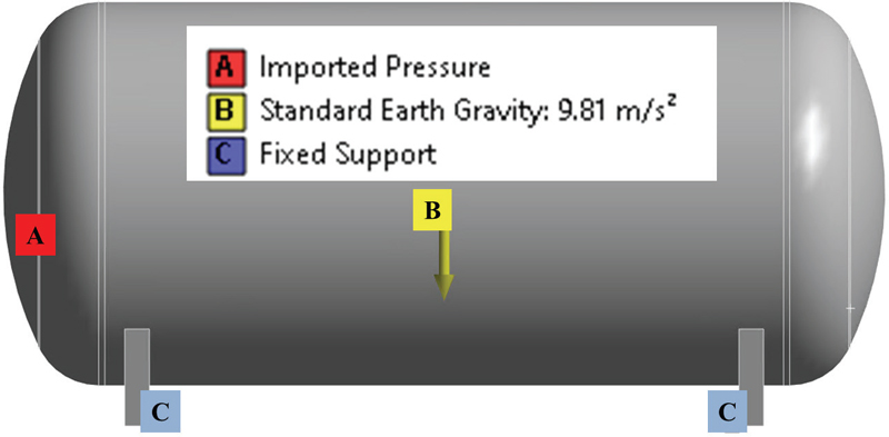
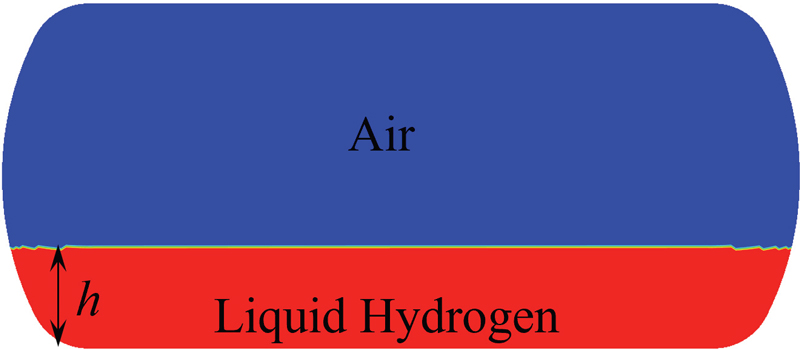
CFD analysis is carried out with pure surge motion. The sloshing dynamics are changed according to the liquid hydrogen level, wave amplitude, and tank motion. Fig. 2 indicates the initial conditions for CFD analysis. Furthermore, the structural analysis was carried out to evaluate stress and deformation within the tank walls. The tank is manufactured using the material ASTM A240. The yield stress and ultimate tensile stress of ASTM A240 are 205MPa and 515MPa, respectively. Fig. 3 shows the boundary condition for the FSI analysis. The discretized grids are necessary for the CFD and FSI analysis. ANSYS ICEM 2022R2(22) is used to prepare the structured grid for CFD analysis.
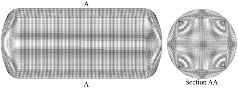
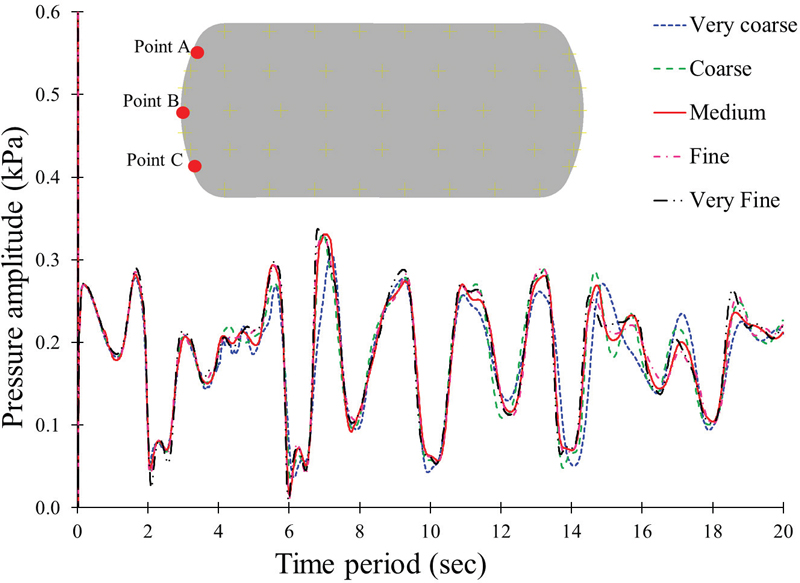
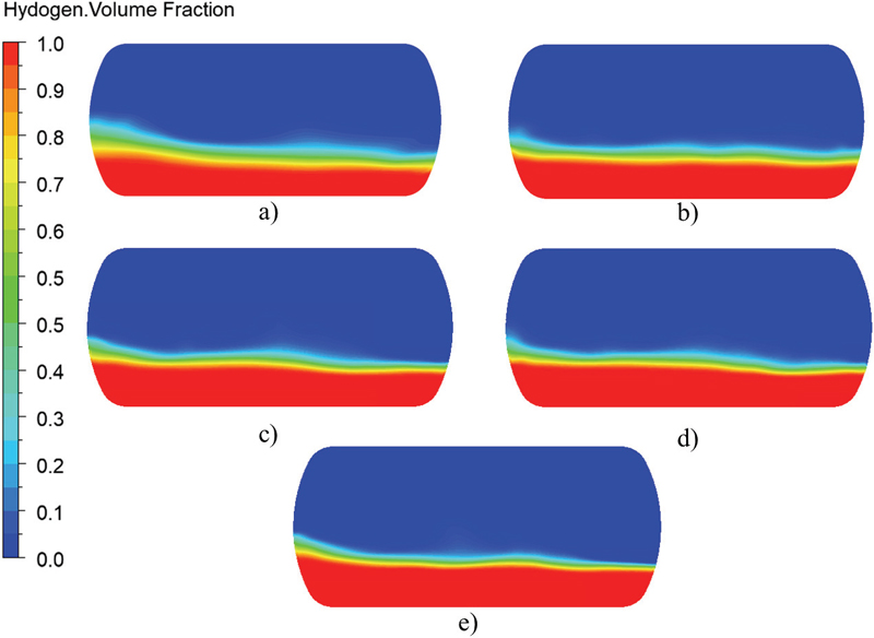
Fig. 4 shows numerical grids used for CFD analysis. The mesh dependency is conducted to show the effect of numerical grids on the CFD analysis. The information on the numerical grids is shown in Table 2. Fig. 5 indicates the pressure distribution at point A with various grid numbers. The pressure distribution is consistent with the numerical grids. The maximum pressure amplitude for very coarse, medium, and very fine mesh are 0.31kPa, 0.33kPa, and 0.34kPa, respectively. The difference in maximum pressure amplitude is comparatively low between various mesh sizes. Fig. 6 elaborates on the volume fraction of liquid hydrogen in the tank with various grid types. The volume fraction distribution in the tank is identical to various grid distributions. The increase in mesh number does not influence the accuracy of CFD analysis. Hence, 1.52million nodes are used for further numerical analysis.
3. Results and Discussion
Sloshing dynamics in the cylindrical tank are affected by various parameters, such as liquid level, wave amplitude, liquid properties, and tank geometry(27).
3.1 Sloshing characteristics by liquid hydrogen level
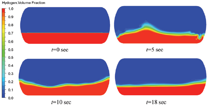
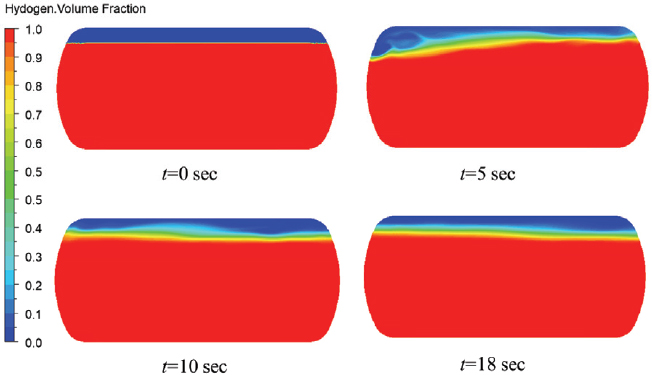
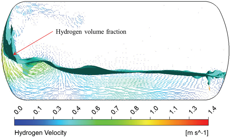
The liquid hydrogen level determines the sloshing dynamics in the storage tank. The liquid filling level from 15 % to 60 % is a partial filling level, and 70 % to 98 % is a standard filling level(28). Therefore, the hydrogen liquid filling of 30 %, 50 %, and 90 % were selected to investigate the sloshing dynamics in partial and standard filling levels. Figs. 7 and 8 show the sloshing dynamics in the tank with filling levels of 30 % and 90 %, respectively. The pure surge motion at a=0.2m is used to evaluate the hydrogen filling level effect in the tank. At h=30 %, the movement of liquid hydrogen is comparatively higher than at h=90 %. Fig. 9 shows the velocity vectors and hydrogen volume movement in the sloshing tank. The liquid hydrogen movement is observed with a 30 % hydrogen volume fraction.
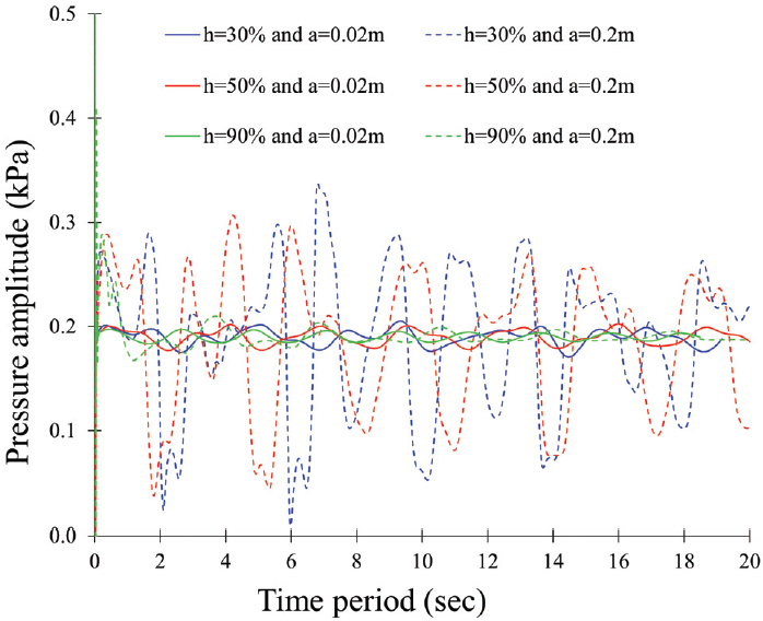
Fig. 10 shows the pressure fluctuation with various hydrogen filling levels. With a=0.2m, a significant pressure fluctuation is observed with hydrogen filling h=30 % and 50 % than in the 90 %.
3.2 Sloshing characteristics by wave amplitude
The wave amplitude determines the excitation force in the tank. Generally, the excitation amplitude is expected to be less than 15 % of the tank height for the proper sloshing dynamics(29). Hence, the wave amplitudes are 0.02m and 0.2m selected for the sloshing dynamics.
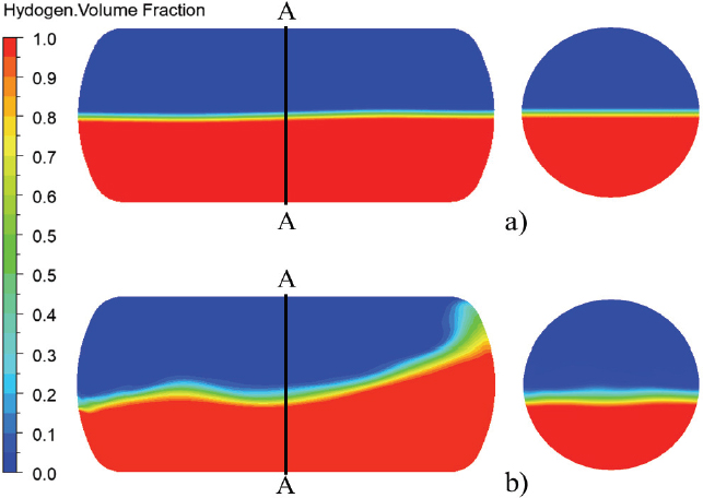
Fig. 10 indicates the pressure distribution at various filling levels and wave amplitudes. The pressure fluctuation is higher when the wave amplitude is higher. At h=30 % and 50 %, a drastic rise in the pressure amplitude occurs when wave amplitude increases from 0.02m to 0.2m. However, at h=90 %, the peak pressure rise occurs at the beginning of the sloshing movement, and the pressure distribution becomes stable very soon compared to the lower filling level. Fig. 11 shows the sloshing motion in the tank with a wave amplitude of 0.02m and 0.2m, respectively. The sloshing movement is negligible in the tank with a=0.02m, but when a=0.2m, the violent movement of the liquid hydrogen is observed in the tank.
The maximum pressure difference between crest and trough is increased from 0.03kPa to 0.31kPa, 0.02kPa to 0.28kPa, and 0.01kPa to 0.03kPa when wave amplitude is increased from 0.02m to 0.2m, at h=30 %, 50 %, and 90 %, respectively. The rise in pressure amplitude is proportional to the wave amplitude at the lower filling level. At h=90 %, the pressure difference is negligible with the increase in wave amplitude.
3.3 Effect of rib structure in sloshing dynamics
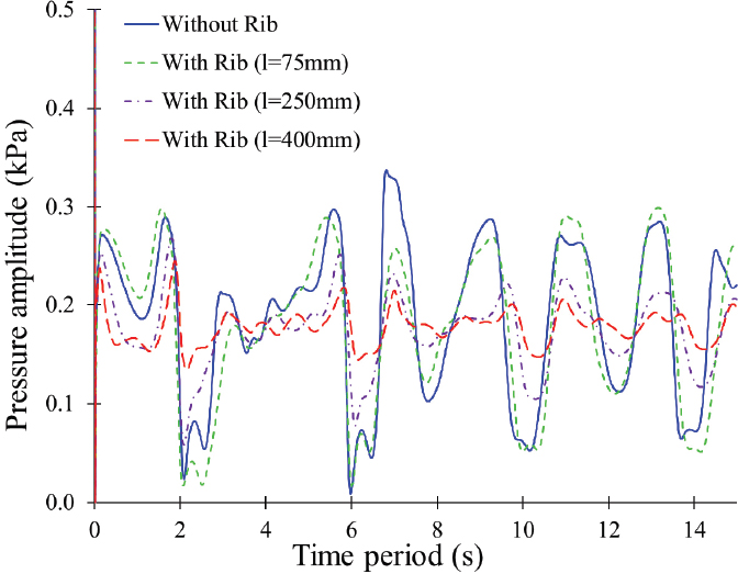
The rib structure is installed in the tank to suppress the sloshing dynamics. Fig. 12 compares the pressure distribution comparison in the tank without and with the rib structure at point A. The pressure distribution comparison indicates that rib structure suppresses pressure fluctuation in the tank. The rib structure helps to reduce the pressure fluctuation in the sloshing tank. The maximum pressure difference between crest and trough are 0.31kPa, 0.29kPa, 0.20kPa, and 0.10kPa in the tank without rib structure, with rib structure l=75mm, 250mm, and 400mm, respectively. The rib structure with l=400mm suppresses the pressure fluctuation effectively compared to the shorter rib structures.
Fig. 13 shows the sloshing dynamics behavior in the tank. The sloshing dynamics show the violent flow behavior in the tank without rib structure. The rib structure with l=400mm reduces the vigorous hydrogen movement efficiently compared to others. Hence, the long rib structure effectively suppresses the vigorous hydrogen movement and pressure fluctuation. Fig. 14 indicates the comparison between sloshing dynamics without and with rib structure. The sloshing movement of hydrogen volume fraction showed that the hydrogen movement is violent in the sloshing tank without rib structure. The installation of a rib structure suppresses the violent hydrogen movement in the sloshing tank. The hydrogen volume fraction is more stable in the sloshing tank with a rib structure than without.
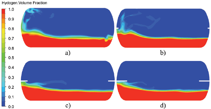
Comparison of sloshing dynamics with surge motion a) without rib b) with rib a=75 mm c) with rib a= 250 mm and d) with rib a=400 mm at h=30 %, a=0.2 m and a=4.5 sec
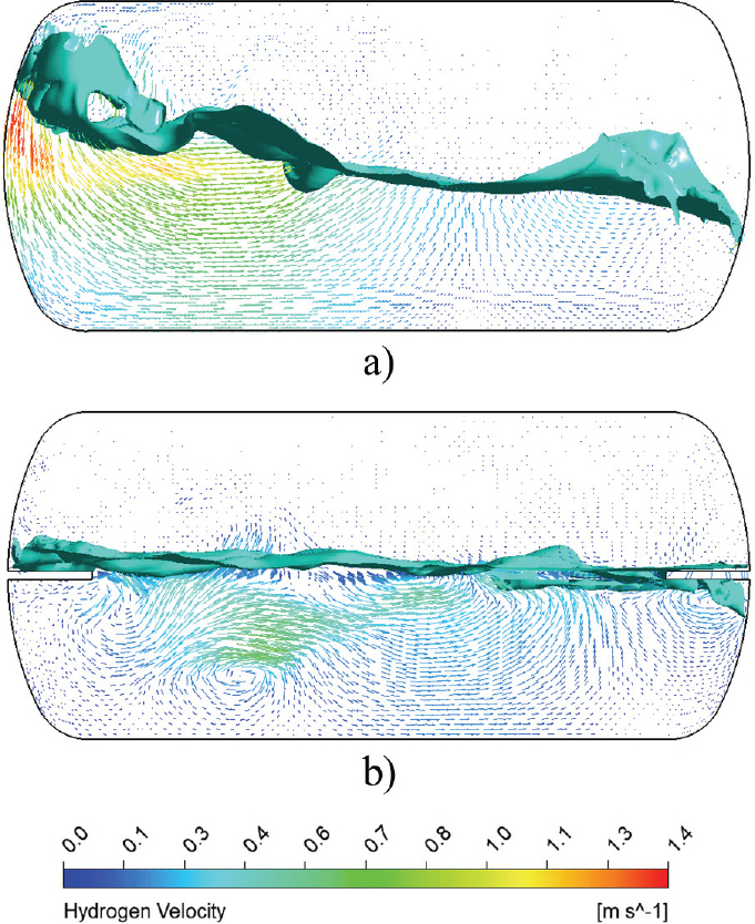
Comparison of velocity vectors in sloshing tank with surge motion a) without rib and b) with rib a=400 mm at h=50 %, a=0.2 m and a=4.0 sec
However, considering the economy of the material cost, a proper length should be determined by optimum design methodology(30-31).
3.4 Structural analysis in the sloshing tank
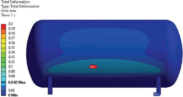
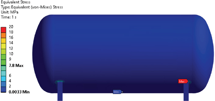
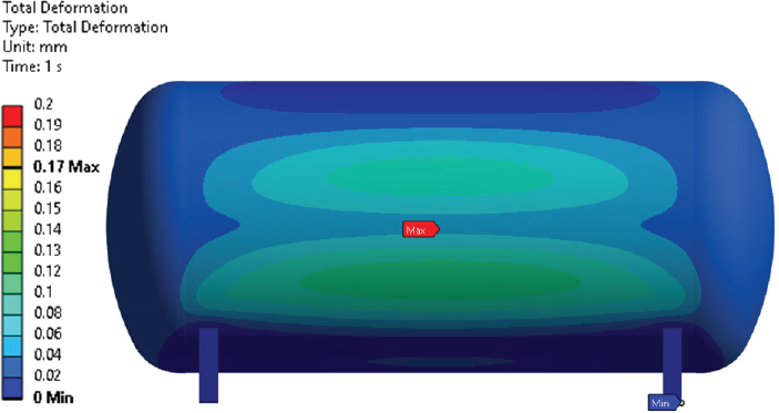
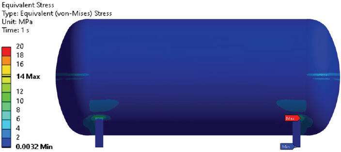
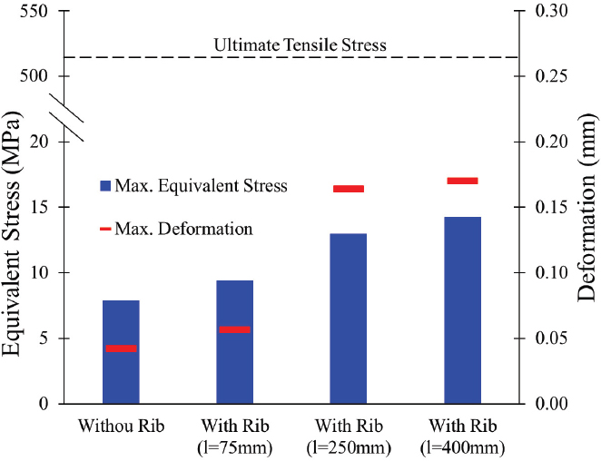
The structural stability of the tank is necessary for the safe transportation of liquid hydrogen. At h=30 %, a=0.2m, and surge motion are selected for FSI analysis of the tank. Fig. 15 shows the total deformation in the sloshing tank. It indicates that the maximum deformation of 0.042mm occurred at the bottom of the tank. Fig. 16 shows the stress distribution on the tank without rib structure. The maximum stress of 7.8MPa is observed at the joint between the stand and the tank. Figs. 17 and 18 show the total deformation and equivalent stress in the sloshing tank with rib structure, respectively. Fig. 17 indicates that a deformation of 0.17mm is observed in the sloshing tank. The maximum equivalent stress of 14MPa is observed at the stand joint and rib structure location.
Fig. 19 shows the FSI analysis comparison in the sloshing tank without and with various rib structures. The rib structure compromises the structural stability of the sloshing tank. The maximum equivalent stress and deformation in the tank increases with an increase in the rib structure length. The maximum equivalent stresses are 7.8MPa, 9.3MPa, 12.9MPa, and 14.2MPa for without rib, with rib l=75mm, 250mm and 400mm, respectively. The maximum equivalent stress is considerably below the ultimate tensile stress of the ASTM A240. The deformation in the sloshing tank is less than 0.20mm in all cases. It concludes that the sloshing tank is structurally stable without and with rib structure.
4. Conclusion
The sloshing dynamics in the hydrogen storage tank with various hydrogen levels, wave amplitude, and wave direction are explained in this study. Wave amplitude has a significant role in sloshing dynamics. The increase in wave amplitude from a=0.02m to 0.2m a maximum pressure amplitude is increased by 88 % and 54 % for h=30 % and 50 % hydrogen filling level, respectively. When h=90 %, there is approximately no change in pressure fluctuation with an increase in wave amplitude from a=0.02m to 0.2m. The pressure amplitude in the sloshing tank wall is comparatively higher, with high wave amplitude at the low filling level. The rib structure is installed in the sloshing tank to suppress the vigorous sloshing movement. The pressure fluctuation is reduced drastically in the tank with a rib structure. The maximum pressure amplitude is suppressed by 15 %, 32 %, and 38 % with rib structure lengths 75mm, 250mm, and 400mm, respectively, with a surge motion, h=30 %, and a=0.2m. The rib structure with l=400mm is significantly better at suppressing violent sloshing movement compared to l=75mm. FSI analysis is conducted to evaluate the equivalent stress and maximum deformation without and with rib structure in the sloshing tank. The equivalent stress in the sloshing tank without rib, with rib l=75mm, 250mm, and 400mm are 7.8MPa, 9.3MPa, 12.9MPa, and 14.2MPa, respectively, with surge motion, h=30 % and a=0.2m. The equivalent stress in the sloshing tank is remarkably below the ultimate stress without and with rib structures. The maximum deformation in the sloshing tank is less than 0.2mm without and with a rib structure. Therefore, the sloshing tank is structurally stable without and with a rib structure. The rib structure is promising to mitigate sloshing in the liquid hydrogen tank.
The optimal design of the rib structure would be performed to reduce the material and manufacturing costs for future works.
Acknowledgments
This research was supported by a grant from Endowment project of “Development of Basic Technologies in Eco-friendly Ship Fuel Reliability and Safety Evaluation” funded by Korea Research Institute of Ships and Ocean Engineering (2520000279(PES5100))
References
-
Zou, C. and Wang, D., 2015, “A simplified mechanical model with fluid–structure interaction for rectangular tank sloshing under horizontal excitation,” Advances in Mechanical Engineering, Vol. 7, No. 5, pp. 1-16.
[https://doi.org/10.1177/1687814015582085]

- Al-Zughaibi, A. I., Hussein, E. Q. and Rashid, F. L., 2021, “Studying and analysis of nonlinear sloshing (vibrating) of interaction fluid structure in storage tanks,” Journal of Mechanical Engineering Research and Development, Vol. 44, No. 7, pp. 180-191.
-
Dumitrache, C. L. and Deleanu, D., 2020, “Sloshing effect, fluid structure interaction analysis,” IOP Conference Series: Materials Science and Engineering, Vol. 916, No. 1, pp. 012030.
[https://doi.org/10.1088/1757-899X/916/1/012030]

-
Wang, B., Xu, T., Jiang, Z., Wang, S., Dong, G. and Wang, T., 2022, “Numerical simulation of sloshing flow in a 2D rectangular tank with porous baffles,” Ocean Engineering, Vol. 256, pp. 111384.
[https://doi.org/10.1016/j.oceaneng.2022.111384]

-
Wu, G. X., Ma, Q. W., & Taylor, R. E. (1998). Numerical simulation of sloshing waves in a 3D tank based on a finite element method. Applied Ocean Research, 20(6), 337-355.
[https://doi.org/10.1016/S0141-1187(98)00030-3]

-
Zhao, D., Hu, Z., Chen, G., Lim, S. and Wang, S., 2018, “Nonlinear sloshing in rectangular tanks under forced excitation,” International Journal of Naval Architecture and Ocean Engineering, Vol. 10, No. 5, pp. 545-565.
[https://doi.org/10.1016/j.ijnaoe.2017.10.005]

-
Popov, G., Sankar, S., Sankar, T. S. and Vatistas, G. H., 1992, “Liquid sloshing in rectangular road containers,” Computers and Fluids, Vol. 21, No. 4, pp. 551-569.
[https://doi.org/10.1016/0045-7930(92)90006-H]

-
Pal, N. C., Bhattacharyya, S. K. and Sinha, P. K., 1999, “Coupled slosh dynamics of liquid-filled, composite cylindrical tanks,” Journal of Engineering Mechanics, Vol. 125, No. 4, pp. 491-495.
[https://doi.org/10.1061/(ASCE)0733-9399(1999)125:4(491)]

-
Wang, J., Sun, S. and Hu, J., 2017, “The coupling analysis of tank motion and sloshing by a fully nonlinear decoupling method,” Nonlinear Dynamics, Vol. 89, pp. 971-985.
[https://doi.org/10.1007/s11071-017-3495-0]

- Khezzar, L., Seibi, A. and Goharzadeh, A., 2009, “Water sloshing in rectangular tanks – an experimental investigation and numerical simulation,” International Journal of Engineering, Vol. 3, No. 2, pp. 174-184.
- Salem, M. I., 2000, “Rollover stability of partially filled heavy-duty elliptical tankers using trammel pendulums to simulate fluid sloshing,” West Virginia University.
-
Liu, D. and Lin, P., 2009, “Three-dimensional liquid sloshing in a tank with baffles,” Ocean Engineering, Vol. 36, No. 2, pp. 202-212.
[https://doi.org/10.1016/j.oceaneng.2008.10.004]

-
Chu, C., Wu, Y., Wu, T. and Wang, C., 2018, “Slosh-induced hydrodynamic force in a water tank with multiple baffles,” Ocean Engineering, Vol. 167, pp. 282-292.
[https://doi.org/10.1016/j.oceaneng.2018.08.049]

-
Akyildız, H. and Ünal, N. E., 2006, “Sloshing in a three-dimensional rectangular tank: Numerical simulation and experimental validation,” Ocean Engineering, Vol. 33, No. 16, pp. 2135-2149.
[https://doi.org/10.1016/j.oceaneng.2005.11.001]

-
Sanapala, V. S., Rajkumar, M., Velusamy, K. and Patnaik, B. S. V., 2018, “Numerical simulation of parametric liquid sloshing in a horizontally baffled rectangular container,” Journal of Fluids and Structures, Vol. 76, pp. 229-250.
[https://doi.org/10.1016/j.jfluidstructs.2017.10.001]

-
Bellezi, C. A., Cheng, L. Y. and Nishimoto, K., 2022, “A numerical study on sloshing mitigation by vertical floating rigid baffle,” Journal of Fluids and Structures, Vol. 109, pp. 103456.
[https://doi.org/10.1016/j.jfluidstructs.2021.103456]

-
Ma, C., Xiong, C. and Ma, G., 2021, “Numerical study on suppressing violent transient sloshing with single and double vertical baffles,” Ocean Engineering, Vol. 223, pp. 108557.
[https://doi.org/10.1016/j.oceaneng.2020.108557]

-
Raja, V. R. and Ponnusamy, P., 2023, “Numerical modelling of nonlinear baffles on sloshing suppression of rectangular tanks under horizontal excitation,” Ocean Engineering, Vol. 267, pp. 113277.
[https://doi.org/10.1016/j.oceaneng.2022.113277]

-
Lei, Y., Zhang, L., Zhong, S. and Huang, B., 2022, “Multi-Objective Optimization of a T-Shaped Anti-Sloshing Baffle Based on NSGA-II,” Frontiers in Energy Research, Vol. 10, pp. 810937.
[https://doi.org/10.3389/fenrg.2022.810937]

- Swedish standards, SS-EN 13530-2, 2003, “Cryogenic vessels - Large transportable vacuum insulated vessel; Part 2: Design, fabrication, inspection and testing,” Swedish Standard Institute.
-
Moss, D. R., 2004, Pressure vessel design manual, Elsevier.
[https://doi.org/10.1016/B978-075067740-0/50002-0]

-
Cheng, Q., Zhang, R., Shi, Z. and Lin, J., 2023, “Review of Common Hydrogen Storage Tanks and Current Manufacturing Methods for Aluminium Tank Liners”, International Journal of Lightweight Materials and Manufacture, Vol. 7, No. 2, pp. 269-284.
[https://doi.org/10.1016/j.ijlmm.2023.08.002]

- ANSYS Inc., 2022, “ANSYS CFX documentation version 2022R2”, http://www.ansys.com, .
-
Hwang, S. Y. and Lee, J. H., 2021, “The numerical investigation of structural strength assessment of LNG CCS by sloshing impacts based on multiphase fluid model”, Applied Sciences, Vol. 11, No. 16, p. 7414.
[https://doi.org/10.3390/app11167414]

-
Liu, L., Feng, D., Wang, X., Zhang, Z., Yu, J. and Chen, M., 2022, “Numerical study on the effect of sloshing on ship parametric roll”, Ocean Engineering, Vol. 247, p. 110612.
[https://doi.org/10.1016/j.oceaneng.2022.110612]

-
Vallés Rebollo, X., Sadeghi, E., Kusano, I. and García-Granada, A. A., 2022, “Study of the Sloshing Dynamics in Partially Filled Rectangular Tanks with Submerged Baffles Using VOF and LES Turbulence Methods for Different Impact Angles”, Computation, Vol. 10, No. 12, p. 225.
[https://doi.org/10.3390/computation10120225]

-
Ünal, U. O., Bilici, G. and Akyıldız, H., 2019, “Liquid sloshing in a two-dimensional rectangular tank: A numerical investigation with a T-shaped baffle”, Ocean Engineering, Vol. 187, p. 106183.
[https://doi.org/10.1016/j.oceaneng.2019.106183]

- Bureau Veritas, 2011, “Design Sloshing Loads for LNG Membrane Tanks”, Guidance Note NI554DTR00E, France.
-
Chung, S. M., Jeon, G. M. and Park, J. C., 2022, “Numerical approach to analyze fluid flow in a type C tank for liquefied hydrogen carrier (part 1: Sloshing flow)”, International Journal of Hydrogen Energy, Vol. 47, No. 8, pp. 5609-5626.
[https://doi.org/10.1016/j.ijhydene.2021.11.156]

-
Shrestha, U., Choi, Y. D., Park, J. and Cho, H., 2021, “Reduced-dimensional design optimization of stay vane and casing of reaction hydro turbines using global sensitivity analysis,” Journal of Mechanical Science and Technology, Vol. 35, No. 4, pp 1487-1499.
[https://doi.org/10.1007/s12206-021-0314-9]

-
Shrestha, U. and Choi, Y. D., 2020, “A CFD-based shape design optimization process of fixed flow passages in a Francis hydro turbine,” Processes, Vol. 8, No. 11, pp. 1392.
[https://doi.org/10.3390/pr8111392]

