A Design of 10 kW Class Counter-Rotating Tidal Turbine Focusing on the Improvement of Operating Performance
Abstract
Tidal turbine, which is relatively similar to wind turbine in term of operational principle, has become a potential solution for the sustainable development of global energy. This paper introduces author’s work on tidal turbine which aims to improve the power efficiency by the adaption of counter-rotating concept. The turbine system is modelled and analyzed using computational simulation commercial code. Compared with other works, the counter-rotating tidal turbine presented here is expected to operate stably with high performance throughout a wide range of tip-speed-ratio. Moreover, the equability of individual performance of each rotor is an advantage.
Keywords:
Counter-rotating, CFD, Tidal power, Tidal turbine, S814키워드:
상반전, 전선유체역학, 조류에너지, 조류터빈1. Introduction
In recent decades, where renewable energy is being put in interest for the sake of global demand, ocean is a considerable resource that shows potential for developing an environmental friendly energy. Covering 70% of the earth surface, ocean is the largest solar collector that holds tremendous energies, a small portion of which would be able to cover the energy need of the entire world. Tidal current is one type of water current that can be exploited for electricity. Tides are the rise and fall of sea levels caused by the combined effects of the rotation of the earth and the gravitational forces exerted by the moon and the sun. The tides occur at an interval of approximately 12 and half hours, so it is more predictable than wind, which highly depends on the weather. Currently, wind turbines with various sizes have become a familiar sight around the world. Their purpose is to collect energy from wind currents. Due to the cost reduction of installation and progressive government policies, wind turbine industry has become a key component of the power production industry in the world. A tidal turbine acts underwater in a very similar way to a wind turbine operates in the air. Instead of extracting energy from the air, a tidal turbine could collect kinetic energy from the water, which is thousand times denser than air, and so even slow moving tides can carry significantly larger energy than wind. Therefore, a tidal turbine has smaller diameter than a wind turbine of the same power output, resulting in lower cost of manufacture and transportation. Due to that, tidal turbine gradually attracts the interest of modern researchers and scientists for its potential.
Similar to wind turbines, one of the major problem of tidal turbine is the limitation of power efficiency. Theoretically, the maximum portion of energy that a single rotor turbine can capture is 16/27 of the total available energy in the stream(1). In actual, this portion is even lower due to various factors and influences. Thus, the wake behind a single rotor contains a large amount of unused energy; part of this energy can be extracted further by installing a second rotor in a proper region. Since the wake behind the first rotor is rotating in the opposite direction to the rotational direction of the rotor, the second rotor should rotate in the same direction as the wake in order to effectively capture the available energy therein. Therefore, counter-rotating concept has been put in interest of many researchers as a positive method to overcome power efficiency limitation. There are several ways to establish a counter-rotating tidal turbine (CRTT) system. However, due to the complex interaction between the coaxial rotors, there have not been any optimum method founded yet. Previously, the same sizing twin rotors system was introduced and showed advantage in compactness but lack of power efficiency improvement, especially for the second rotor at the downstream location for both wind and tidal cases(2),(3). This paper introduces a new CRTT design that has a significant improvement of counter-rotated rotor which is expected to contribute larger amount of power to the whole CRTT system.
2. Turbine Design
The major component of a turbine-like machine is the blade which directly affects the device’s performance. Basically, blade can be derived from hydrofoil profile by various methods. In this paper, blade elemental momentum theory (BEMT) is applied for the turbine design. CRTT is horizontal axis type turbine, therefore turbine design should meet the requirement of generating high and optimum lift force. S814 is a suitable hydrofoil which is design by National Renewable Energy Laboratory (NREL) of USA. Both the front and rear rotor blades in this CRTT system are derived from S814 hydrofoil.
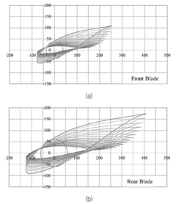
Rear rotor is larger in size in order to effectively capture tidal power within the stream. NREL S814 hydrofoil is also a popular interest of many recent works, i.e. the experiment of Barltrop et al.(4), or various works of Clarke et al.(5). The major advantage of the S814 is its minimized sensitivity of maximum lift coefficient to roughness effects(6). In this study, S814 hydrofoil is selected for its durability as a thick hydrofoil and its compatibility in tough operating condition as underwater environment. Full blade sections derived from this hydrofoil are illustrated in Fig. 1 which shows shape and size of each hydrofoil section from blade root to the tip for 10 kW scale tidal turbine. It is designed to operate at tip-speed-ratio (TSR) of 3 (rotational speed is about 45.83 rpm for front rotor which rotates counter- clockwise and 28.64rpm for the rear one which rotates clockwise). The modeling process results in design parameters as shown in Table 1.
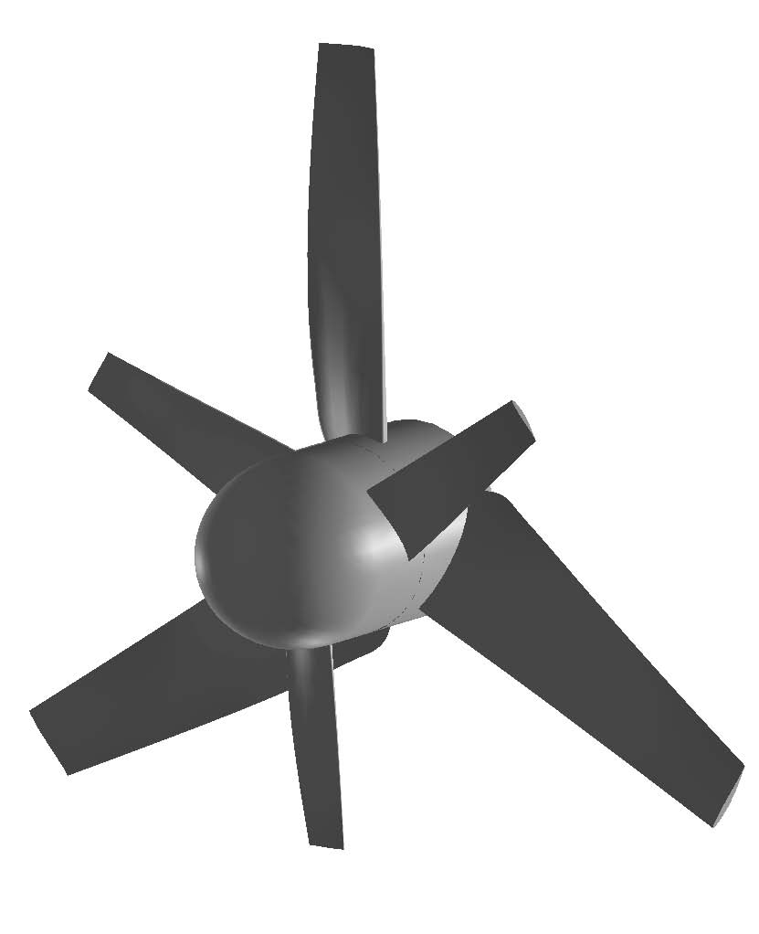
For non-dimensional expression, front rotor diameter is presented by D. Hence, rear rotor diameter is set to 1.6D, and the space between two rotors is 0.2D. The completed assembly of full rotor CRTT system is illustrated in Fig. 2. With enlarged blades at rear rotor, the CRTT is not only able to capture energy in the upstream wake, but also to absorb a part of energy in the stream escaped from front rotor’s sweeping periphery. The connection between blades and hub is fixed since the pitch change function is not applicable for the turbine in this study. Hub size dominates 1/5 of rotor’s total size and is large enough to install generator as well as gearing mechanism and fittings. Since the aim of this work is the computational fluid dynamics (CFD) of CRTT, there is no extra structural effect or equipment is taken into account.
3. Computational Model
3.1 Meshing
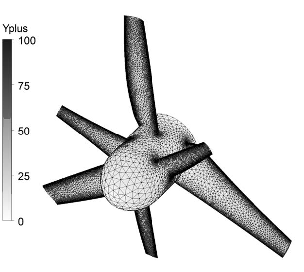
Power performance and characteristics of the CRTT are analyzed using CFD commercial code, the ANSYS 14. Meshing is done using ANSYS MESHING. Mesh dependency study was carried out and the independency was achieved at mesh size of 6.1 million nodes (about 23 million tetra elements). The full rotor simulation requires high computational effort but can bring about more accurate results. Fig. 3 illustrates mesh formation for the rotor which shows very dense and fine development of elements. Yplus value at most parts of the rotor region are below 10.
3.2 Calculation Domain and Boundary Conditions
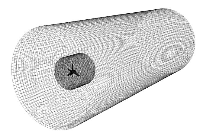
The computational domain is shown in Fig. 4. The domain has cylindrical shape and is sized 4.8D × 25.6D (Radius × Length). This is suitable for full rotor simulation and is large enough to capture the wake characteristics with high accuracy. The far-field region is gridded using multi-zone hexa mesh, while the turbine region is high density tetra mesh with well-developed boundary layer as described above. Inlet boundary is normal speed, outlet boundary is static pressure, and opening boundary is set to “Opening Pressure and Direction”. The blades and hub are all no-slip wall boundaries. The mesh connections between both rotors (front and rear) and between each rotor with the flow field are general connection interface boundaries and are set to frozen rotor for frame change/mixing model. The fluid is sea water at 25oC, turbulence model is shear stress transport (SST) with turbulence intensity is set to low (1%) for the whole flow-field. Simulation is done in steady state by ANSYS CFX Solver and is carried out for a wide range of TSR as viewed in Table 2. Solver iteration is set to 10000, time scale is kept as low as 0.025s for convergence.
4. Results and Discussions
4.1 Flow Patterns
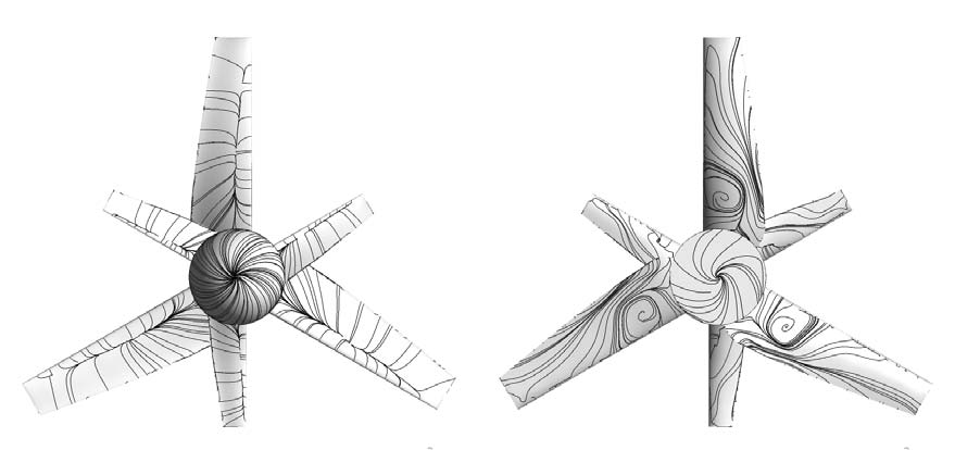
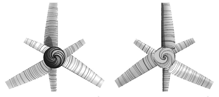
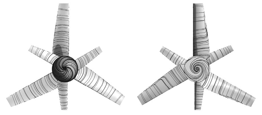
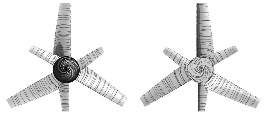
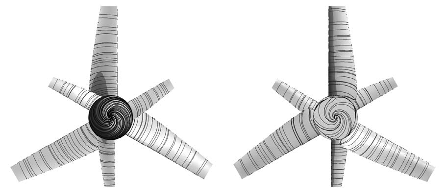
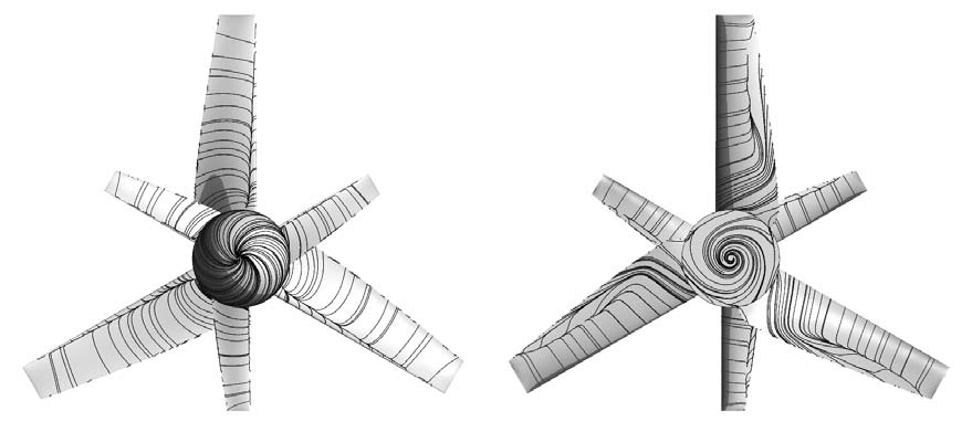
The visualization of flow patterns at different TSRs are in turn shown in Fig. 5 to Fig. 10. These figures present the surface streamlines of relative water velocity (velocity in rotating frame) which are distributed over the blades and hub. In all cases, the view of blade’s pressure side is oriented at the left of the figure and the one on the right views blade’s suction side.
At TSR 1 (highest tidal inflow velocity), it is clearly seen that there is flow detachment at the pressure side. On the other hand, vortex is formed at suction side (mainly at root part) and there is the existent of radial flow at all blades. Usually, fluid within turbine’s wake region should flow following the blade’s rotational movement. In this case, the streamlines on suction surface tends to move in radial direction from the root of blades toward the tips. Radial flow has no effect in transferring water’s kinetic energy into rotor’s torque due to the escape of water from the wake’s core region. The main reason for this is extremely high inflow tidal speed, the inflow speed up to around 6m/s is considered very high in terms of physical understanding. Thus, under such high speed flow, water is quickly detached from blades and this phenomenon may not beneficial to the absorption and exchange of power.
At TSR 2 (Fig. 6), the streamlines already became well developed. The distribution of streamlines at blade’s pressure and suction sides become more uniform without any abnormal or strange effect. At higher TSR (from 3 to 5), the patterns look similar and there is also no significant difference between front and rear rotor blades. At operating TSR (theoretically TSR 3, and is based on single rotor design), there is a tiny sign of radial flow at trailing edge of rear blade’s suction side. The cause of this is not clear and possibly due to computational error or minor meshing problem. Moreover, the finest state of streamlines seem to be found at TSR 4. With this, the CRTT's optimum operating point can be shifted. By examining the energy transfer efficiency, the effect can be figured out but in general, the interaction between rotors does have a certain changes to overall performance of the CRTT.
At the highest TSR (lowest tidal inflow velocity), the streamlines are no longer maintain the smoothness and stability. Although there is no formation of vortex or complicated flow, there is the appearance of radial flow that is similar to the pattern at TSR 1. However, the strength and intensity of the effect are weaker and mainly noticeable at rear rotor’s suction side.
4.2 Power Efficiency
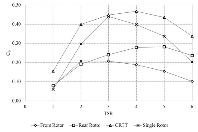
Power performance of S814 CRTT is evaluated by power coefficient CP which is calculated and expressed in Fig. 11. The figure expresses CP as a function of TSR and shows individual performance of each rotor as well as the combined performance of the CRTT system.
Based on previous studies(2),(3), a single rotor turbine can operate efficiently, and extra-added rotor can only contribute a small increase of efficiency to the device. Moreover, there may be effects that are not advantageous for each rotor in counter-rotating assembly, i.e. local vortex or back flow. Such effects may cause deficiency in both rotors’ operation.
Besides, because of the wake’s physical characteristics, escaped water from front rotor contacts the rear rotor in different angles of attack and influences the aerodynamic performance of the rear rotor blades. Thus, the individual CP of both front and rear rotors are under 0.3 throughout the range which are lower than their true capability in separated installation operation. However, the overall CP of CRTT is seen to be high all in all. From the finding at streamline characteristics, TSR 4 is the most efficient point which has the maximum CP very close to 0.5. The performance is seen to be good since there is only a slightly decrease of CP at the vicinity (TSR3 and TSR 5). Even at the highest TSR, power efficiency of CRTT is in an acceptable value. At TSR 1, the turbine’s performance is poor as CP is as low as 0.15. This is reasonable to what has been seen previously at the flow patterns.
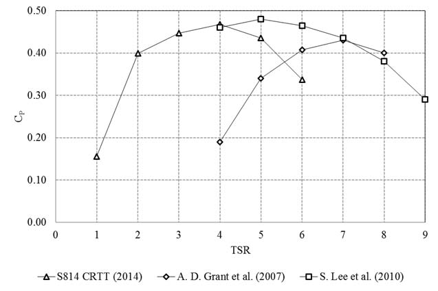
Fig. 11 also presents the performance of S814 tidal turbine operating as single rotor device with the same design as front blade. Compared with the CRTT, single rotor turbine has the maximum CP at TSR 3 and this point is significant higher than the rest. When it comes to CRTT system, the front rotor's performance drops in about half of its capability seen in single operation. The installation of counter-rotated rotor at given distance in fact does influence the operation of upstream rotor and thus decreases its power efficiency. These results are reasonable to characteristics of flow patterns discussed above, where high efficiency is found at cases with well-developed streamlines. In same sizing design, the rear rotor’s performance is not so highlighted and mainly beneficial at low TSRs. Compared to recent works of other researchers as Sutikno et al.(7), Grant et al.(8), Kumar et al.(9) and Lee et al.(10), S814 CRTT shows similar or even more promising performance. Figure 12 shows several recent researches’ results in comparison with S814 CRTT. Lee et al.’s counter-rotating turbine is slightly more efficient than S814 CRTT, but their work is done for wind case. The other studies have one common, that is the operating range is mostly at high TSR region where either tidal current is low (low power output) or rotational speed is high (disadvantage for durability and structural concerns).
The configuration of S814 CRTT in this study results in bigger rear rotor but shows more promising power performance and more importantly the trend is maintained throughout a wide range of TSR and both rotors have stable equal performance with less unbeneficial interaction. With the high performance at various TSRs, we can use this device widely and efficiently at varied tidal current conditions.
In actual, other than power efficiency there are many concerns about CRTT needed to be fully discovered. Nevertheless, the S814 CRTT shows high potential for further development and improvement.
5. Conclusions
This paper introduces a computational evaluation of counter-rotating application for tidal current turbines which focus on introducing and analyzing a proposed design for rear rotor as a solution to enhance power efficiency. In summary, the following conclusions are given.
1) The proposed design of tidal turbine is able to capture tidal energy up to 33 - 48% of available source under a wide variety of tidal stream velocity ranging from 1 to 3m/s.
2) The design of CRTT in this study shows less complex interaction between rotors which allows them to evenly co-operate and contribute to the overall performance of the system efficiently.
3) The size of rear rotor disables the compactness of CRTT system but does contribute to the improvement of power performance.
The CRTT in this paper is computational model and its capability has not been fully comprehended yet since various factors were excluded, i.e. distance between rotors, other selections and arrangement of counter-rotating assembly. These problems should be investigated and taken into account in future work to discover the optimal design for CRTT. The results of this study help contributing to the present development of tidal turbine as the potential method of tidal energy conversion to serve the future demand of renewable energy.
Acknowledgments
This research was a part of the project titled “Interaction Study for Optimal Tidal Farm,” funded by the Ministry of Oceans and Fisheries, Korea.
References
-
Ragheb, M., and Ragheb, A. M., (2011), “Wind Turbines Theory–The Betz Equation and Optimal Rotor Tip Speed Ratio”, Fundamental and Advanced Topics in Wind Power, ISBN 978-953-307-508-2 p19-38.
[https://doi.org/10.5772/21398]

-
Hoang, A. D., and Yang, C. J., (2014), “Design and Performance Evaluation of a 10 kW Scale Counter- Rotating Wind Turbine Rotor”, Journal of the Korean Society of Marine Environment & Safety, 20(1), p104-112.
[https://doi.org/10.7837/kosomes.2014.20.1.104]

-
Hoang, A. D., and Yang, C. J., (2014), “Design and Performance Evaluation of a 10 kW Scale Counter- Rotating Tidal Turbine”, The KSFM Journal of Fluid Machinery, 17(1), p47-63.
[https://doi.org/10.5293/kfma.2014.17.1.047]

-
Barltrop, N., et al. , (2007), “Investigation into Wave-current Interactions in Marine Current Turbines”, Proc. IMechE Vol. 221 Part A: J. Power and Energy, p233-242.
[https://doi.org/10.1243/09576509JPE315]

- Clarke, J. A., et al. , (2007), “Development of a Contra-Rotating Tidal Current Turbine and Analysis of Performance”, Proceedings of the 7th European Wave and Tidal Energy Conference (EWTEC), Southampton.
- Somers, D. M., (1997), “Design and Experimental Results for the S814 Airfoil”, National Renewable Energy Laboratory (NREL), NREL/SR-440-6919.
- Sutikno, P., et al. , (2011), “Design and Blade Optimization of Contra Rotation Double Rotor Wind Turbine”, International Journal of Mechanical & Mechatronics Engineering IJMME-IJENS, 11(01), p17-27.
-
Grant, A. D., et al. , (2007), “Design and Testing of a Contra-Rotating Tidal Current Turbine”, Proceedings of the Institution of Mechanical Engineers, Part A: Journal of Power and Energy, 221(2), p171-179.
[https://doi.org/10.1243/09576509JPE296]

- Kumar, P. S., et al. , (2013), “Computational and Experimental Analysis of a Counter-Rotating Wind Turbine System”, Journal of Scientific & Industrial Research, 72, p300-306.
-
Lee, S., et al. , (2010), “Analysis of Aerodynamic Characteristics on a Counter-Rotating Wind Turbine”, The Proceeding of the International Renewable Energy Conference and Exhibition 2008, Current Applied Physics, 10(2), Supplement, p339-342.
[https://doi.org/10.1016/j.cap.2009.11.073]

- Somers, D. M., (2004), “The S814 and S815 Airfoils”, National Renewable Energy Laboratory (NREL), NREL/SR-500-36292.
