Relationship between Cavitation Incipient and NPSH Characteristic for Inverter Drive Centrifugal Pumps
Abstract
The purpose of this study is to understand the cavitation phenomena in centrifugal pumps through computational fluid dynamics method. NPSH characteristic curve is measured from different flow operating conditions. Steady state, liquid-vapor homogeneous method with two equations transport turbulence model is employed to estimate the NPSH curve in centrifugal pumps. The Rayleigh-Plesset cavitation model is adapted as source term for inter-phase mass transfer in order to understand cavitation phenomena in centrifugal pumps. The cavitation incipient curve is clearly estimated at different flows operating conditions. A relationship is made between cavitation incipient and NPSH curve. Also the effects on water vapor volume fraction and pressure load distributions on the impeller blade are also described.
Keywords:
Cavitation Model, Cavitation Incipient, NPSH Characteristics, Numerical Study키워드:
캐비테이션 모델, 캐비테이션 시작점, 유효흡입수두특성, 수치적 연구1. Introduction
Cavitation phenomena plays an important role in the design and development of turbomachines such as pumps, turbines, hydrofoil etc.. Cavitation is a process of vapor formation and disappearance of the vapor phase of a liquid when it is subjected to reduce and subsequently increased pressure at constant temperatures.(1) The appearance and disappearance of regions with vapor is a major of noise, vibration, erosion and efficiency loss in hydraulic machinery.(2) In many technical applications cavitation is hardly avoidable at all operating conditions. When it occurs it needs to be controlled. in order to reduce these unfavorable effects, technology for accurate prediction and estimation of cavitation are very important in the development of high-speed fluid devices such as centrifugal pump.(3) Due to the importance of the cavitation phenomenon and the great process in the cavitation and turbulence models, numerical simulations have been widely used to investigate the cavitation flow field in the turbomachinery such as centrifugal pumps.(4,5) In order to clarify and understand the behavior of cavity flow, cavity flow models and analytical methods for numerical simulations have been proposed.(6,7)
An extensive amount of literature exists on experimental studies of cavitation and most of are on hydrofoils. Arakeri and Acosta (1973) have studied the viscous effects in the inception of cavitation and development on two axisymmetric bodies using the flow visualization method.(8) They found cavitation inception occur in the laminar boundary layer separation region.
Bakir et al. (2004) coupled the Rayleigh-Plesset equation to the flow solver and computed void fraction in pump inducer.(9)Medvitz et al. (2002) performed the cavitation analysis in centrifugal pump using multiphase CFD and pointed out the head inception and breakdown point.(10) Bruno et al. (2009) have studied on different NPSH characteristics in centrifugal pump.(1)Kim et al. (2012) have studied on unsteady cavitation analysis in centrifugal pump and made a good comparison with experimental data but not focused on the cavitation inception.(11)
To account for the cavitation dynamics in a flexible manner, recently a transport equation model is developed. In this approach volume or mass fraction of liquid (and vapor) phase is convicted. Singhal et al. (2002), Kunz et al. (2000), Shyy et al. (2002) have employed similar models based on this concept with differences in the source terms.(12~14)
The present study is focused to understand the cavitation phenomena in inverter drive centrifugal pumps by using numerical methods. In the numerical prediction, Singhal et. al.(12) proposed R-P cavitation model, and two-phase homogeneous liquid-vapor CFD method are used. The NPSH characteristic curve is estimated from head drop curves under different flow conditions and a relationship is made with cavitation incipient curve. In addition, the effects on water vapor volume fraction and pressure load distributions on the impeller blade is also described.
2. Numerical Methodology
The fluid with cavitation in the pump is considered as two phase homogeneous, mixed medium of liquid and vapor. The governing equations are given as
| (1) |
| (2) |
where ρm and μm are the mixture density and dynamic viscosity, u is the velocity, p is the pressure, and μt is the turbulent viscosity respectively and subscripts i, j, k denotes the axes directions. Mixture density and turbulence viscosity are defined as
| (3) |
The volume fractions are related with the vapor mass fraction f. The growth and collapse of a fluid bubble is given by a modified Rayleigh-Plesset equation, which is governed by transport equation controlling vapor generation and condensation
| (4) |
The source term Γ is the diffusion rate, Re and Rc represents evaporation and condensation respectively. The phase transformations are given as
| (5) |
where values of the empirical factor constants Ce and Cc for 0.02 and 0.01 the gas mass fraction fg=1.5x10⁻⁵, the surface tension coefficient σ=0.0717 N/m, pv denote vaporization pressure, and k is the turbulent kinetic energy. if p<pv evaporation occurs and if p>pv condensation occurs.
3. Meshing and Boundary Conditions
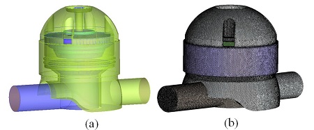
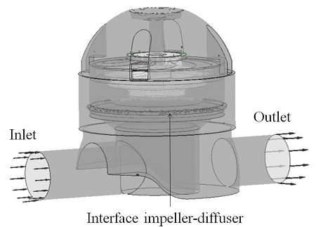
The inverter drive centrifugal pump model (impeller, diffuser) was used to understand the cavitation phenomena is shown in Fig. 1(a). The model pump was meshed by ANSYS ICEM-CFX (Ansys Inc. 2013, USA) based on finite volume method (FVM).(15) The pump model impeller, diffuser, and casing were meshed and a mesh dependency test was carried out under noncavitating conditions at design operating flow and found the pressure drops error was less than 1%. The total meshed element and nodes were 4477248 and 1417827. The unconstructed prim meshing of centrifugal pump is shown in Fig. 1(b). Under the cavitating condition, impeller domain was rotating part with z-axis and the rotational speed was 3600 rpm with different flow operating conditions, and diffuser was stationary domain. A frozen rotor was applied to couple the rotation and stationary domain. The impeller-diffuser of the pump domain is shown in Fig. 2. The inlet boundary was static frame total pressure and mass flow rate was imposed at outlet boundary. All boundary walls were assumed smooth wall with no-slip condition. The frozen rotor simulation selected for the steady state analysis at given rotational speed. SST turbulence model.(15,16) was used to solve the turbulence phenomena of fluid. High resolution for the advection scheme, first order for turbulence numeric and SIMPLEC algorithm were considered in solver setting. The residual value was of 1x10⁻⁵ controlled by convergence control solver. Table 1 is shown the design specification of centrifugal pump model for simulations.
4. Results and Discussion
4.1 Cavitation incipient and NPSH characteristic
The NPSH is the difference between absolute stagnation pressure in flow at the pump suction and the liquid vapor pressure. The NPSH is defined as.(1)
| (6) |
where pin is the static pressure at the pump inlet, pv is the vapor pressure depends on the liquid temperature.
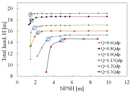
Fig. 3 shows the estimated results of head drop lines under different flows operating conditions. The head drop lines were estimated to occur by gradually reducing the net positive suction head. From figure it was observed that the head breakdown occurred at lower NPSH at each head drop line. With the decreased of NPSH, resulting in a decrease of head. To understand the phenomena of this, there was cavitation bubble formed in the pump on the impeller blade (Suh et al.).(17) On the other hand, flow rate changed before design point, cavitation started at lower NPSH but after design point it was occurred at higher NPSH.
There are typical critical characteristics which can be identified for centrifugal pumps such as incipient of net positive suction head, and 3% head drop. From a set of head drop curves (see Fig. 3), it is possible to estimate the NPSH characteristics as a function of through different flow rates. The curve could be for instance the NPSH corresponding to 3% head drop.
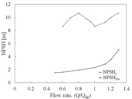
NPSHre is the minimum suction pressure necessary to ensure proper pump operation. The NPSHre head drop curve shown in Fig. 4. NPSHre was done by determining from cavitation head drop lines at 3% head drop. The curve shown to steep rise of the 3% head brake down. After deign point curve shown exponentially increased because cavitation occurred at higher NPSH and the occurrence of cavitation affected on the pump impeller pressure side.
The reason why a centrifugal pumps requires a positive suction head is because it is impossible to design a centrifugal pump with no pressure drop between the suction inlet and its minimum pressure point, which normally occurs at the entrance to the impeller vanes. If the pressure at this point drops below a certain level then fully formed cavitation would be occurred.
Cavitation incipient is that point where the water and vapor are in equilibrium with the equilibrium vapor pressure. Cavitation incipient was observed in the pump impeller where the first vapor bubbles were generated. It constitutes the minimum NPSH required by the pump to operate without cavitation bubbles. Fig. 4 is shown the NPSHi characteristics of the centrifugal pump.
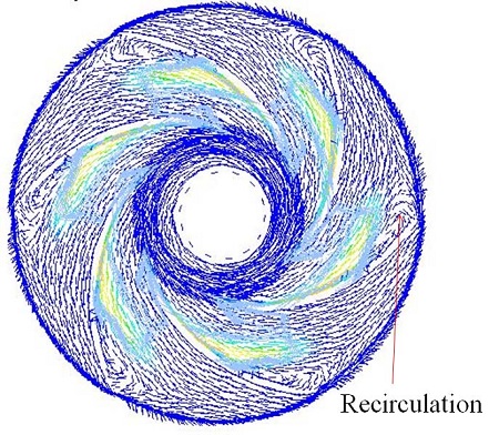
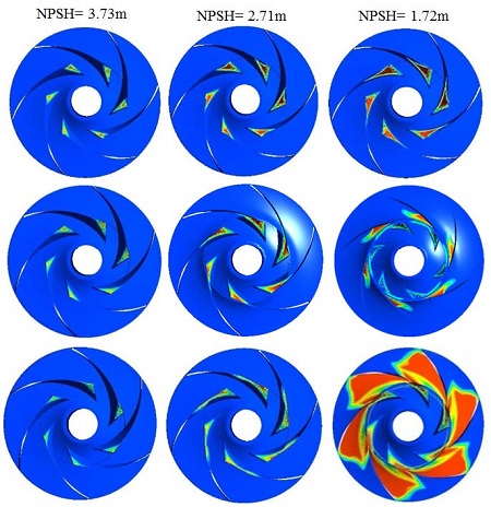
From Fig. 4, the NPSHre was seen to follow the steep rise of the NPSHi curve. Below best cavitation point (design point) the inception curve raised until a maximum point is reached which was associated with the onset of completely suction head breakdown and formed recirculation in the inlet throat area as shown in Fig. 5. Figure 6 shown the different cavitating behavior according with NPSH and flow rates.
4.2 Pressure effects on impeller blade
The pressure load distribution is one of important for cavitation analysis because there is directly effect on cavitation conditions and it’s related to static pressure of the pump. Fig. 6 is shown the pressure loading distribution at design flow rate at different NPSH values. The impeller loading is the pressure difference between the static pressure on the pressure zone and the suction zone. In Fig. 6 the stream wise (0-1) location is the dimensionless distance from the inlet to outlet of the impeller ranging from 0 to 1. From figure the pressure loading was affected on the suction side of the impeller, reducing the suction effect near the blade leading edge. The pressure distribution on blade loading increases from the leading edge to the neighborhood of the trailing edge. The initial decrease of NPSH had no effect on the impeller blade loading. When the value of NPSH decreases into 2.71 m, the pressure at the suction side (leading edge) was almost keep constant, but the development of cavitation had no impact on the blade pressure distribution from streamline (-) 0 to 0.4. After that, when the value of NPSH=1.72 m, i.e. at the location from 0.4 to 1, the progression of the cavitation had a significant effect on the impeller blade loading at the pressure suction side. At head breakdown, it could be observed that cavitation also appears on the inlet part of the blade pressure side. Fig. 6 shown the cavitating behavior on the impeller blade.
5. Conclusion
A Reyleigh-Plesset cavitation model has been used to simulate the ANSYS-CFX code. Steady state simulations have been performed with shear stress transport turbulence model to understand the cavitation phenomena at different flow operating conditions. The propagation of cavitation on the impeller blade from suction leading edge to trailing edge was observed. The NPSH characteristics were estimated from different flows at design angular velocity. The computed incipient and 3% net positive suction head was estimated clearly. Numerical simulation can help to provide the useful information to understand the cavitation phenomena and NPSH characteristics of the pump.
References
- Schiavello, B., and Visser, F. C., (2009), “Pump Cavitation —Various NPSHR Criteria, NPSHA Margins, and Impeller Life Expectancy”, In Proceedings of the 25th International Pump Users Symposium, p113-144.
- Japan Association of Agriculture Engineering Enterprises, (1991), “Pumping Station Engineering Hand Book”, Tokyo, p50-90.
-
Shin, B. R., Yamamoto, S., and Yuan, X., (2004), “Application of preconditioning method to gas-liquid two-phase flow computations”, J. of Fluids Engineering, ASME, 126, p605-612.
[https://doi.org/10.1115/1.1777230]

-
Pouffary, B., Patella, R. F., Reboud, J. L., and Lambert, P. A., (2008), “Numerical simulation of 3D cavitating flows analysis of cavitation head drop in turbomachinery”, Journal of Fluids Engineering, 130(6), p301-310.
[https://doi.org/10.1115/1.2917420]

-
Coutier-Delgosha, O., Fortes-Patella, R., and Reboud, J. L., (2003), “Evaluation of the turbulence model influence on the numerical simulations of unsteady cavitation”, Journal of Fluids Engineering, 125(1), p38-45.
[https://doi.org/10.1115/1.1524584]

-
Passandideh-Fard, M., and Roohi, E., (2008), “Transient simulations of cavitating flows using a modified volume of fluid (VOF) technique”, Int. J. Computational Fluid Dynamics, 22(1~2), p97-114.
[https://doi.org/10.1080/10618560701733657]

- Senocak, I., and Shyy, W., (2001), “Numerical simulation of turbulent flows with sheet cavitation”, Int. Symp. on Cavitation, A7, p2-8.
-
Arakeri, V. H., and Acosta, A. J., (1973), “Viscous effects in the inception of cavitation on axisymmetric bodies”, Journal of fluids engineering, 95(4), p519-527.
[https://doi.org/10.1115/1.3447065]

-
Bakir, F., Rey, R., Gerber, A. G., Belamri, T., and Hutchinson, B., (2004), “Numerical and experimental investigations of the cavitating behavior of an inducer”, International Journal of Rotating Machinery, 10, p15-25.
[https://doi.org/10.1155/S1023621X04000028]

-
Medvitz, R. B., Kunz, R. F., Boger, D. A., Lindau, J. W., Yocum, A. M., and Pauley, L. L., (2002), “Performance analysis of cavitating flow in centrifugal pumps using multiphase CFD”, Journal of Fluids Engineering, 124(2), p377-383.
[https://doi.org/10.1115/1.1457453]

-
Kim, D. H., Park, W. G., and Jung, C. M., (2012), “Numerical simulation of cavitating flow past axisymmetric body”, International Journal of Naval Architecture and Ocean Engineering, 4(3), p256-266.
[https://doi.org/10.3744/JNAOE.2012.4.3.256]

-
Singhal, A. K., Athavale, M. M., Li, H., and Jiang, Y., (2002), “Mathematical basis and validation of the full cavitation model”, Journal of Fluids Engineering, 124(3), p617-624.
[https://doi.org/10.1115/1.1486223]

-
Kunz, R. F., Boger, D. A., Stinebring, D. R., et al , (2000), “A preconditioned Navier-Stokes method for two phase flows with application to cavitation prediction”, Computers & Fluids, 29(8), p849-875.
[https://doi.org/10.1016/S0045-7930(99)00039-0]

-
Senocak, I., and Shyy, W., (2002), “A pressure based method for turbulent cavitating flow components”, Journal of Computational Physics, 179(2), p363-383.
[https://doi.org/10.1006/jcph.2002.6992]

- Ansys Inc, (2013), ANSYS-CFX (CFX Introduction, CFX Reference guide, CFX Tutorials, CFX-Pre User's Guide, CFX-Solver Manager User's Guide, Theory Guide), release 14.5, USA.
-
Georgiadis, N. J., Yoder, D. A., and Engblom, W. B., (2006), Evaluation of modified two-equation turbulence models for jet flow predictions, AIAA Journal, 44(12), p3107-3114.
[https://doi.org/10.2514/1.22650]

-
Suh, S. H., Kim, H. H., Cho, M. T., and Shin, B. R., (2015), “Cavitating Flow Analysis of Multistage Centrifugal Pump”, KSFM J. of Fluid Mach, 18(1), p65-71.
[https://doi.org/10.5293/kfma.2015.18.1.065]

