A Study on the Effect of Port Area of Blade on the Performance of Francis Hydro Turbine
Abstract
As a key component of a Francis turbine facility, the runner performance plays a vital role in the performance of the turbine. It is effective and successful to design a Francis turbine runner blade with good performance by one dimensional hydraulic design method. On the basis of one dimensional hydraulic analysis, there are a lot of parameters of the internal flow passage shapes determined by experience. Among those parameters, the effect of port area of blade on the performance of a Francis turbine is investigated in this study. A given Francis turbine model was selected for investigating the port area of blade on the performance. The result shows that the effect of port area of runner blade on the outflow angle from runner passage on the performance is quite significant. A correct exit flow angle reduces the energy loss at draft tube, which has the best efficiency of the turbine model.
Keywords:
Francis Hydro Turbine, Loss Analysis, Performance, Runner Blade Design키워드:
프란시스수차, 손실 해석, 성능, 러너 블레이드 설계1. Introduction
Hydropower is one of the most important renewable energy source among the other sources. Francis turbines are applicable to a wide range of head and specific speeds. Their wide range of applicability and easier structural design makes Francis turbines more advantageous than other hydraulic turbines. As a key component of a Francis turbine facility, the runner performance plays a vital role in the performance of the turbine. It is effective and successful to design a Francis turbine runner blade with good performance by one dimensional hydraulic design method. On the basis of one dimensional hydraulic analysis, there are a lot of parameters of the internal flow passage shapes determined by experience.
Many researchers studied the Francis turbine parameters on the performance by numerical method. Jeon et al(1) investigated the flow characteristics in a Francis turbine with various blade profiles of NACA 65 and NACA 16 series. They showed that proper blade profile can provide about 1.5% upgrade in peak efficiency. Kaewnai et al(2) improved Francis turbine efficiency at the desired head by correction of meridional plane and runner blade inlet angle. For the one dimensional hydraulic design, the runner blade angle at leading and trailing edges can be defined by calculation of Euler’s head. However, the exit flow angle from runner passage does not easily match with 90°, even the blade outlet angle is designed from the assumption of u 2 νu 2=0, which has the best efficiency point(3-5). The effect of port area of runner blade on the exit flow angle from runner passage is very important.
In this study, the effect of port area of blade on the performance of a Francis turbine is investigated to design the runner blade. A Francis turbine with specific speed of Ns=120 m-kW was selected for investigating the port area of blade on the performance. The runner blade inlet and outlet angles were designed by calculation of Euler’s head, and the port area of blade was modified by keeping the inlet and outlet angles of the blade constant.
2. Francis Turbine Model and Numerical Methods
2.1 Francis turbine model
In this study, a Francis turbine model with the specific speed of Ns=120 m-kW was selected to investigate the effect of blade angle distribution on the performance. The design point of the Francis turbine is at He=35 m for the effective head, Q=0.25 m3/s for the water flow rate and the rotational speed is N=1,200 min-1. The inlet diameter of the runner is L1=310 mm, the outlet diameter of that is De=250 mm. The number of runner blade is Z=15. In addition, the number of guide vane is Zg=16, and the number of stay vane is Zs=16.
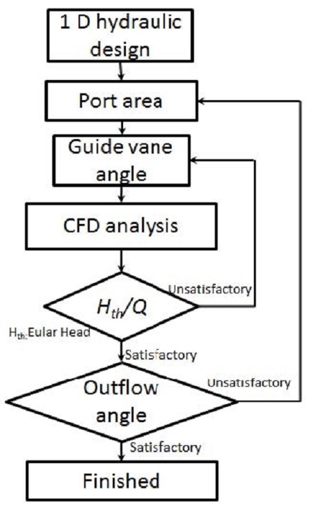
Fig. 1 shows the Francis turbine runner blade design flow chart. There are two redesign processes in this design flow chart. The turbine head is controlled by the guide vane opening under the condition of design point. The outflow angle from runner outlet is controlled by the port area and blade outlet angle. Moreover, the blade outlet angle can be calculated by the Euler head equation. Therefore, the port area is modified to investigate the performance of the Francis turbine.
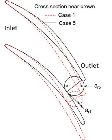
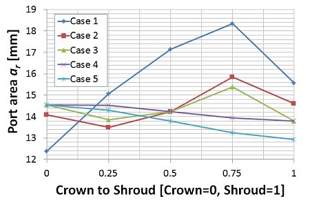
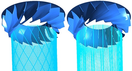
Fig. 2 shows the definition of the runner blade port area. The port area of the runner blade is located at the exit of the runner flow passage, which is the minimum area at the runner flow passage. Therefore, the dimension of port area plays a very important role on controlling absolute exit velocity from runner passage. The exit angle from runner passage is 90° only with correct absolute exit velocity. Fig. 3 shows the port area distribution from crown to shroud in the runner flow passage. There are 5 cases with different port areas. The port area reduces from Cases 1 to 5 near the shroud.
In this study, in order to investigate the effect of port area on the performance of the Francis turbine, the other parameters have to be kept same, such as the flow rate, head and rotational speed. The flow rate and the rotational speed are controlled by the boundary condition of numerical analysis. In order to match the head, the several guide vane opening are tried. Therefore, there are several trial cases conducted to match the heads to each port area as shown in Table 1.
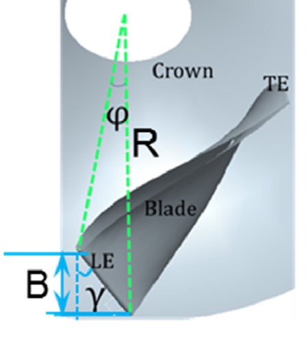
The definition of the blade turning angle is shown in Fig. 4. The relationship between γ and φ can be described by the following equation.
| (1) |
Where, γ is lean angle, φ is turning angle, R is the radius of runner, and B is the runner inlet passage height.
The turning angle of Cases 1a to 5a is 0˚, which means that the leading edge of those cases is perpendicular to the crown and shroud. The turning angle of Cases 5b is 10°. That blade is called the “X blade”(6). The port area of Cases 1a to 5a is different. The port area of Cases 5a and 5b is same, only the turning angle is different between those two cases.
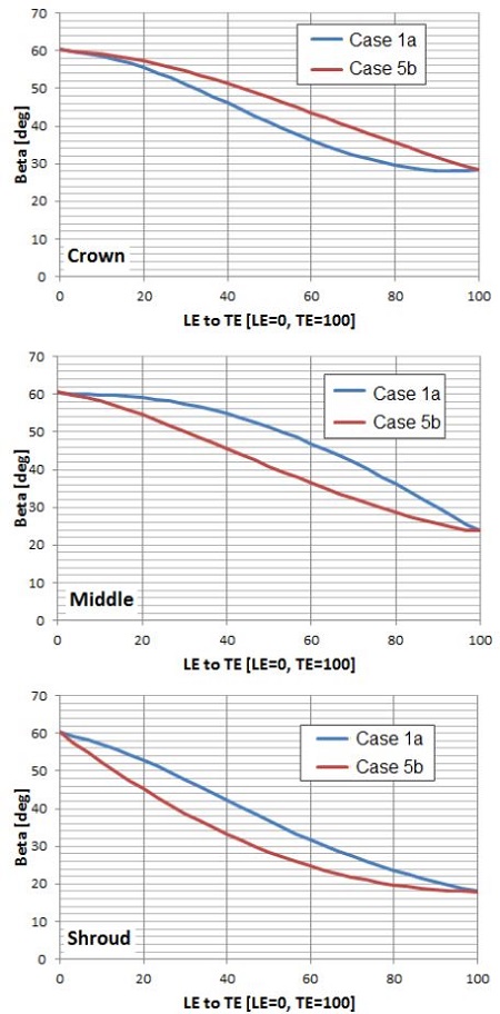
Fig. 5 shows the blade angle distribution from the leading to trailing edge for Cases 1a and 5b. It can be seen that the beta angle at leading and trailing edge is same for the Cases 1a and 5b. However, the beta angle distribution from leading to trailing edge is different.
2.2 Numerical method
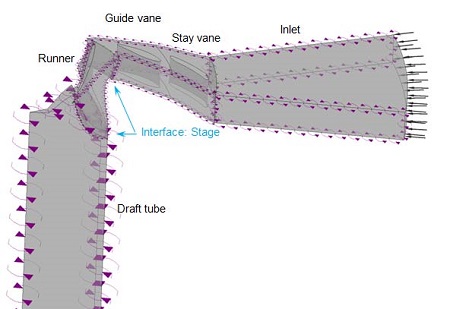
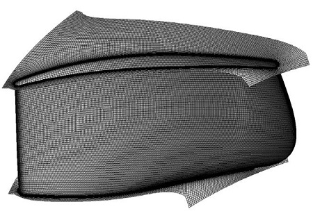
Computational Fluid Dynamics (CFD) analysis is a very useful tool for predicting hydro machinery performance at various operating conditions(2-5) Commercial code of ANSYS CFX(7) is employed to predict the characteristics of the Francis turbine with different blade loading. The 1 pitch of flow passage (1 stay vane, 1 guide vane and 1 runner blade flow passage) was selected for the numerical analysis as shown in Fig. 6. The general connection was set as “stage” condition between the rotational area and the fixed area in the flow field for the steady state calculation(7). The total pressure boundary condition was applied at the inlet of the calculation domain, and the static pressure was set for the outlet of the domain. According to the previous study(8-9), the Shear stress transport (SST) turbulence model is adopted as turbulence model, which has been well known to estimate both separation and vortex occurrence on the wall of a complicated blade shape. The mesh dependence is done for validation test of the numerical method. The efficiency of turbine becomes constant after the mesh number excess of 2.6×10⁶ elements. Therefore, the mesh number of about 2.6×10⁶ elements is selected for all the cases, for which the averaged non-dimensional wall distance y+ is about 3 for runner blade surface. Fig. 7 shows the fine numerical grids of the runner blade.
3. Results and Discussion
3.1 Head selection
In this study, there are some assumptions for the initial runner design. The leakage efficiency and the mechanical efficiency are assumed as ηv=0.985 and ηm=0.99, respectively. Therefore, the Euler head can be calculated according to the pressure loss as following:
| (2) |
| (3) |
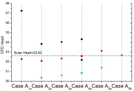
In order to keep the same Euler head of Francis turbine with different port area from Cases 1a to 5b, the different guide vane opening is investigated for each case as shown in Table 1 and Fig. 8. Changing guide vane angles for each case until the Euler head is satisfied. The red marker is the satisfactory Hth, although there is slight deviation for some cases.
3.2 Efficiency curve
Considering only the hydraulic loss, the turbine efficiency is calculated by the following equation (4):
| (4) |
Where, T is the torque of runner; ω is the angular speed of runner rotation on its own axis; ρ is the water density; g is the gravitational acceleration; Q is the flow rate; H is total head of turbine.
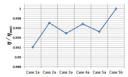
Fig. 9 presents the efficiency curves by the different port area from Cases 1a to 5b. It can be seen that there is best efficiency (ηb) difference among the Cases 1a to 5b. The maximum efficiency (ηmax) is located in Case 5b.
3.3 Loss analysis
For the pressure loss analysis, the equation is defined as following:
| (5) |
| (6) |
where HLoss is the pressure loss for the inlet, stay vane, guide vane and draft outlet flow passage, Hloss runner is the pressure loss for the runner passage.
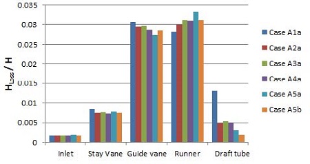
Fig. 10 presents the pressure loss distribution on each component from inlet to outlet. It can be seen that the pressure losses exist to a large extent at the guide vane and runner passage. Around pressure loss ratio of 0.03 consumes on the guide vane and runner passage. However, there is relatively low pressure loss distribution on the inlet, stay vane and draft tube. The pressure loss of Case 1a on the draft tube is the largest in comparison with the others.
3.4 Outflow pattern
In order to investigate the loss in the draft tube by different port area, the outflow pattern at the inlet of the draft tube is investigated.
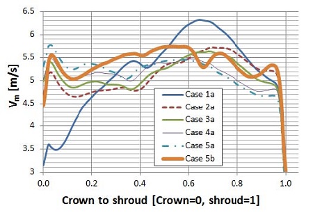
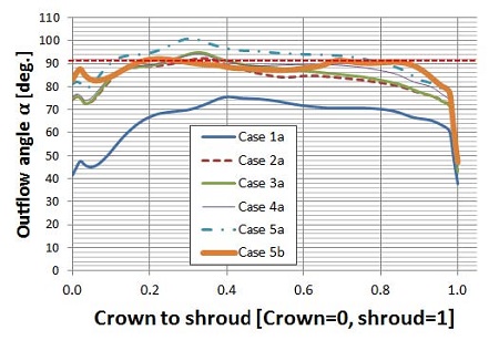
Fig. 11 presents the meridional velocity (Vm) distribution. It can be seen that there is considerable variation of the meridional velocity distribution of Case 1a from crown to shroud. The meridional velocity of Case 5b relatively keeps constant from crown to shroud. This is the reason that the exit flow angle (α) has only small deviation distribution from 90° from the crown to shroud as shown in Fig. 12. A correct exit flow angle plays a role of reducing the loss at draft tube and improving the efficiency of the turbine. Fig. 13 shows the streamline distribution in the draft tube. It is clearly indicated that the streamline of Case 1a in the draft tube shows large swirl flow, which increases the loss at the draft tube and this reduces the head and decreases the output power. The port area of the runner is dissatisfactory, which causes the outflow angle farther away from 90° and the large swirl flow in the draft tube. However, by modifying the port area to a correct extent (Case 5b), there is vertically straight streamlines in the draft tube, and exit flow angle is around 90°. The effect of modifying the port area on correcting the exit flow angle is significant in reducing the swirl flow.
4. Conclusions
The port area of runner blade plays a role of correcting the outflow angle from runner passage. Outflow angle at 90˚ is obtained by modifying the port area of runner blade to achieve the best efficiency.
The swirl flow is suppressed by the modifying the port area. Moreover, the effect of port area on the loss distribution in the draft tube is significant. The loss can be reduced to a minimum extent after modifying the port area.
Acknowledgments
This work was supported by the New and Renewable Energy of the Korea Institute of Energy Technology Evaluation and Planning (KETEP) grant funded by the Korea government Ministry of Trade, Industry and Energy (No.2013T100200079).
References
- Jeon, J. H., Byeon, S. S., and Kim, Y. J., (2013), “Numerical Study on the Flow Characteristics of the Francis Turbine with Various Blade Profiles”, ASME 2013 Fluids Engineering Division Summer Meeting.
-
Kaewnai, S., and Wongwises, S., (2011), “Improvement of the Runner Design of Francis Turbine using Computational Fluid Dynamics”, American J. of Engineering and Applied Sciences, 4(4), p540-547.
[https://doi.org/10.3844/ajeassp.2011.540.547]

- Nechleba, M., (1957), Hydraulic Turbine: Their Design and Equipment, ARTIA, Prague.
- Radha Krishna, H. C., Hydraulic Design of Hydraulic Machinery, International Editorial Committee Chairman, Duan, C G., Secretary, A P Boldy.
- Mei, Zu-yan., (1991), Mechanical design and manufacturing of hydraulic machinery, Avebury Technical.
- Andritz Hydro, Hydro News, No. 15/5-2009, p6-7.
- ANSYS Inc, (2012), “ANSYS CFX Documentation”, Ver. 12, http://www.ansys.com.
-
Wei, Q., Zhu, B., and Choi, Y. D., (2012), “Internal Flow Characteristics in the Draft Tube of a Francis Turbine”, Journal of the Korean Society of Marine Engineering, 36(5), p618-626.
[https://doi.org/10.5916/jkosme.2012.36.5.618]

-
Wei, Q., and Choi, Y. D., (2013), “The Influence of Guide Vane Opening on the Internal Flow of a Francis Turbine”, Journal of the Korean Society of Marine Engineering, 37(3), p274-281.
[https://doi.org/10.5916/jkosme.2013.37.3.274]

