Tidal Farming Optimization around Jangjuk-sudo by Numerical Modelling
Abstract
This study presents an approach of tidal farming optimization using a numerical modelling method to simulate tidal energy extraction for 1MW scale tidal stream devices around Jangjuk-sudo, South Korea. The utility of the approach in this research is demonstrated by optimizing the tidal farm in an idealized scenario and a more realistic case with three scenarios of 28-turbine centered tidal array (named A, B and C layouts) inside the Jangjuk-sudo. In addition, the numerical method also provides a pre-processing calculation helps the researchers to quickly determine where the best resource site is located when considering the position of the tidal stream turbine farm. From the simulation results, it is clearly seen that the net energy (or wake energy yield which includes the impacts of wake effects on power generation) extracted from the layout A is virtually equal to the estimates of speed-up energy yield (or the gross energy which is the sum of energy yield of each turbine without wake effects), up to 30.3 GWh/year.
Keywords:
Energy Yield, Tidal Energy Extraction, Tidal Farming Optimization, Tidal Stream Device, Wake Modelling키워드:
에너지 산출, 조류에너지 추출, 조류단지 최적화, 조류발전기, 후류모델1. Introduction
Together with the increasing cost of energy, tidal turbines are becoming a competitive and promising choice for renewable electricity generation. Tidal current energy is one of the best of the potential resources since: (a) its capture ability does not rely upon the large scale constructions required for tidal energy absorption, making it more environmentally friendly; (b) it is highly predictable relative to wind energy,(1) with higher rates of energy extraction possibility using smaller converters due to the 800-1000 times greater density of sea water compared to air; and (c) more importantly, tidal current energy is less vulnerable to seasonal and global climate changes than most other renewable energy sources. Alongside these positives, there exists the potential for seabed effects, including sediment accumulation and associated ecological changes, in the lee of tidal current generators once energy harvesting begins.
Recently, the existing flow field in area of interest for tidal current turbine development using a numerical modelling approach are being examined.(2-3) The site characterization typically seeks to assess the potential power available to hydrokinetic turbines and to understand flow features that are pertinent to the extraction ability of the available power. However, it is also well-known that the presence of turbines alters the flow fields, with implications both for the environment(4-5) and for the power production. Tidal farms consisting of hundreds of tidal turbines must typically be deployed at a particular site for reducing the fixed costs of turbine installation and grid connection. This emerges the question of where to place the turbines within the site and how to tune them individually in order to maximize the power output. Finding the optimal configuration is a huge importance as it could substantially change the energy captured and possibly determine whether the project is economically viable. However, the determination of the optimal configuration is difficult due to the complexity of flow interactions between turbines and the fact that the power output depends sensitively on the flow velocity at the turbine positions. Currently, there are several numerical studies on wind and tidal farm optimization being carried out using different numerical methods for particular sites in the world. For instance, 12 MW of wind capacity and 20 MW tidal arrays were studied on energy yield for collocated offshore wind and tidal stream farms at the MeyGen site in the Pentland Firth (Sudall et al., 2015)(6) using AWS OpenWind with a standard eddy-viscosity wake modelling for a wind farm and Reynolds-averaged Navier Stokes - Blade Element Momentum (RANS-BEM) CFD modelling for tidal current turbine farm; or a study using TELEMAC for tidal current turbine farm in Paimpol-Brehat (Brittany)(7), or a research using Regional Ocean Modelling System (ROMS) on tidal turbine power capture and impact in an idealized channel (M. Thyng et al., 2012)(8), or tidal turbine array optimization study was done by Funke et al., 2014(9) using the adjoint approach, and so on.
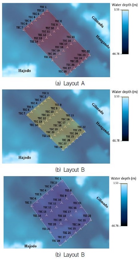
In this paper, we present an efficient approach to energy yield prediction by means of evaluating array scale interactions and the potential effects, which the array layout has on energy yield. The approach is implemented by an application of numerical modelling method. The inputs used for providing the tidal currents across a site inside Jangjuk-sudo are collected from the hydrodynamics modelling data using ADCIRC. Tidal farm optimization was done for three configurations of 28-turbine centered tidal farm, including layout A with area of 3.66 km2, layout B with area of 2.68 km2, and layout C with area of 3.94 km2. These farm consist of seven devices in equally lateral spacing installed in four rows in equally longitudinal spacing. The basis of tidal turbine layout arrangement is primarily relied upon the tidal energy resource potential analysis (such as tidal current direction, tidal speed, etc.), and device constraints (depth for deployment, lateral and longitudinal spacing, etc.) given as an indispensable input for tidal farm optimization.
2. Numerical Modelling Method
The inputs for the resource are used to develop a three-dimensional model of the undisturbed flow around the array. This model is constructed in the frequency domain via a process of binning the temporally varying flow results of a hydrodynamic model into a number of speed bins. The flow speed bins should be defined according to the long-term current speed over the project lifetime such that the inter-annual variation resulting from the influence of the tidal nodal factors is captured.
The tidal energy converter (TEC) performance characteristics and the incident flow onto a group of turbines under boundless conditions are calculated. The power, thrust and efficiency of the TEC are calculated using the performance information that is inputted into the interface. These thrust coefficient and ambient turbulence intensity are then used to predict the changes in flow field around the turbines using wake models. The wake model yields the downstream wake deficit, using the incident flow field and the rotor thrust. The deficit enables the prediction of the incident flow onto downstream turbines. The inclusion of the ambient turbulence intensity is an important parameter in the wake model, and is used to predict the increase in turbulence intensity experienced by the downstream turbines. Once array interactions are resolved, the power performance of the array can be obtained for each flow speed bin. This then allows the energy yield of the proposed project to be evaluated by combining the frequency of occurrence and the power output per speed bin.
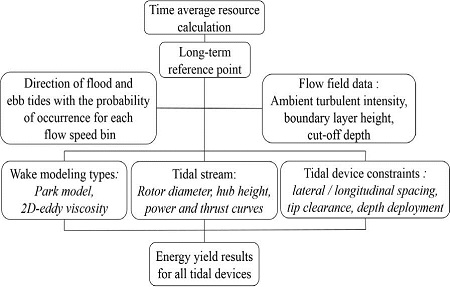
Fig. 1 expresses a diagram of energy yield analysis in this study for tidal farming optimization energy yield values include a key output from the hydrodynamic modelling data enabling the effect of wake losses and array efficiency to be evaluated for different array layouts. The turbine utilizes an evaluated power-weighted speed and power curve to calculate the mean power output for each turbine at each defined “flow state”. The mean powers of each device for each state are then combined with the occurrence distribution to yield an overall array energy yield. The total array energy extraction is the sum of all the individual devices and can be described by the Eq. (1) below:
| (1) |
Where Earray is the gross energy output for the array. The following terms are also defined:
- is the mean power output and fik is the frequency of occurrence;
- j is the device index which provides a reference number of the device in the array, and Nt is the total number of devices in the array;
- i is the flow speed index related to the speed bin (for example 1.95 - 2.05 m/s) under consideration, and Nv is the total number of flow speeds in the long-term flow speed distribution for each flow direction;
- k is the index for flow direction, with Ndir being the total number of flow speed directions.
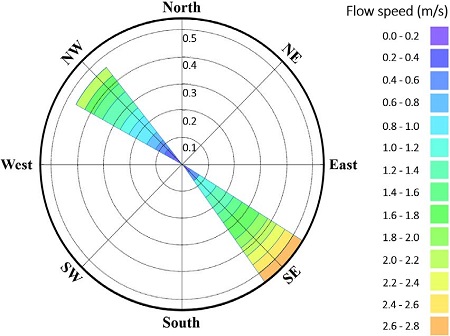
The index for flow direction k is derived from the provisional tidal characterization. Both at-sea measurements and numerical modelling show that the maximum velocity during ebb are somewhat higher than during flood at the Jangju-sudo site, the tidal rise is asymmetric in magnitude and direction. The flow is bi-directional with two main directions: around 133o clockwise from North during ebb (i.e. South-East) and around 310o during flood (i.e. North-West), which means that the ebb and flood are not perfectly at opposite angle. Besides, The numerical model shows that velocity is not uniform over the zone and it can vary a great deal within distances of only hundreds of meters.
When analyzing the array yield production, the net energy output (or wake energy which includes the impact of wake effects on power generation) as well as array and bathymetry efficiency need to be calculated for each individual turbine and the tidal array as a whole. The wake effect calculation employs a systematic approach where each turbine is considered in turn in order to increase axial displacement downstream. By this method, the first device is assumed to be unaffected by wake effects. After that, the first device’s incident flow speed and thrust coefficient are calculated. Then, the wake of the first device is modelled and the parameters which describe its wake are stored. The effect of all upstream wakes on subsequent downstream turbines can then be modelled. At each stage of speed and turbulence incident on these turbines can be determined, solely due to the upstream turbines being considered. The research employs “Park model” for wake modelling type to simulate the wake effects. The downstream tidal speed is calculated using the following formula:
| (2) |
Where U∞ is the axial flow speed incident on the turbine (m/s), Ct is the thrust coefficient, n is the wake decay constant, d is the downstream distance (m), and D is the rotor diameter (m).
3. Input Parameters
3.1 Time-averaged Energy Resource Data
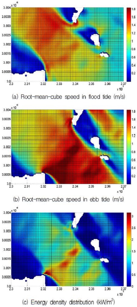
The purpose of the tidal energy resource data is to inform suitable locations where devices should be installed. Two measurements of the available power are the root-mean-cube of the flow speed (URMC) in two principle directions (flood and ebb tides) at the site and the energy density as depicted in Fig. 2(10). The URMC is calculated by averaging over a time history of flow speed cubed at the site. The cube root of the average is then taken and has the same unit as speed.
As depicted in Figs. 2(a) and 2(b), the dark red color is representative of the highest URMC of the tidal stream flow. In contrast, the dark blue color represents the lowest tidal speed value. It is obvious that in these two figures, the tidal speed intensively concentrates on the ebb direction more than the tidal stream during flood tide. Basically, these numerical visualizations of tidal flow here are suitable to at-sea observed data which are collected by KHOA.
About energy density map in Fig. 2(c), the tidal energy potential is virtually distributed on the middle of the map. The data of tidal energy resource will give a quick and detailed assessment of tidal energy potential inside Jangju-sudo for tidal farming in this study. This is also an important input to select the area candidates where contain high energy density within tidal stream flow such that the best location for tidal farming may be found, and reduce the time of tidal farming process.
3.2 Interactive Inputs
In addition to specifying the source of the hydrodynamic modelling, information derived and concerning the measurement location should be inputted. This includes the location of the measured data, usually given in the same coordinate system as the bathymetry and hydrodynamic modelling, as well as the long-term resource, and observed power law and turbulence intensity profiles. Many studies have conducted with several power laws due to impact of seabed surface roughness, such as 1/7th power law, 1/10th power law and logarithm power law.(11,12) In this study, 1/7th power law velocity profile is selected for most calculations. According to A. D. Hoang’s works(13) and Bahaj’s works(11), there was no significant difference among three curves of 1/7th, 1/10th and logarithm power laws.
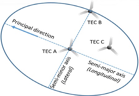
Table 1 shows the long-term resource information for the planned area of tidal farming. Tidal ellipse at long-term reference point inside Jangjuk-sudo channel is expressed in Fig. 3.
The long-term resource is typically based on a harmonic model of the flow currents derived from the measurement data. Moreover, the principal directions (oN) should be taken into account such that the long-term resource data, power law profiles, turbulence intensity and flow model data can all be aligned with one another.
These variables concerning the description of a single tidal stream device which can be of arbitrary definition. The parameters which are usually obtained from a technology manufacturer, consist of the device geometry such as hub height, rotor diameter as well as the power performance. In this study, the turbine with 1MW output scale was taken into account and its geometry parameters are shown in Table 2.
A further set of inputs is the geometric device constraints. These define the basic constraints such that deployment of the TECs is realistic when considering the expected energy yield of a layout. If a device fails a constraint check, the device will be switched off for the energy yield calculation. Table 3 shows the device constraints parameters used in the study. Fig. 5 shows the tidal devices installed inside the Jangjuk-sudo, including layout A, B and C, with device installation constraints that must be suitable to the requirements as shown in Fig. 4. In three configurations, layout A has the longest longitudinal spacing (about 900 m), but layout C has the longest lateral spacing (about 300 m). Layout B is the smallest, both in lateral and longitudinal distances, only 2.68 km2 in area against 3.66 km2 in area of layout A and 3.94 km2 in area of layout C.
4. Results and Discussions
4.1 Wake Effects Analysis
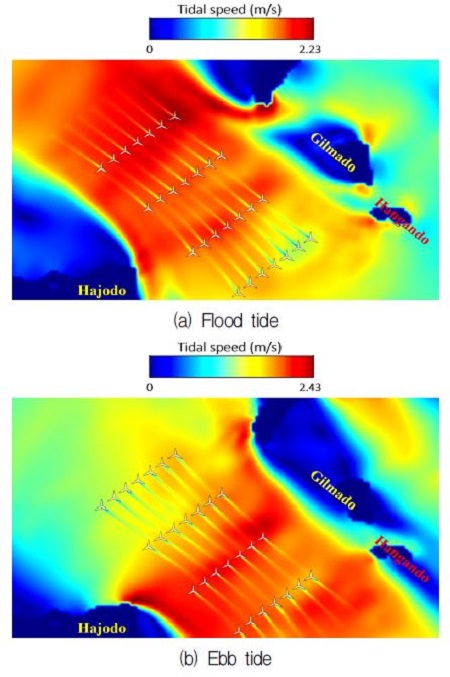
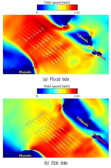
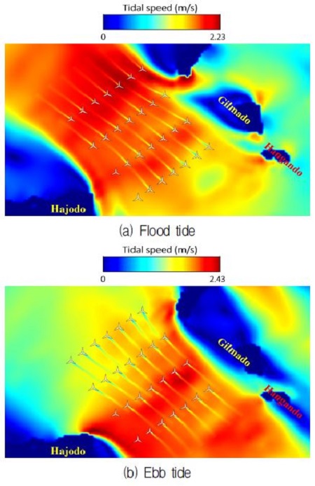
Fig. 6 to 8 show the wake flow visualizations of 28-turbine arrays installed in a centered formation simulated in two directions of tidal stream (flood and eb tides), including layout A, B and C, respectively.
As depicted in Fig. 6, the wake flow from the upstream devices in both tidal directions seems not to affect the downstream turbines. In can be simply explained that layout A has the longest longitudinal spacing, and this could reduce the influence of upstream devices wake flows on the downstream devices. Moreover, it is obvious that the devices No. 15 to 21 are installed at a location where intensively concentrates high tidal stream velocity during ebb and flood tides. In the other words, these turbines will absorb high tidal current energy comparing to the other devices. Meanwhile, the tidal stream devices are positioned at low tidal speed consisting of the devices No. 6 and 7 (during ebb), No. 22, 23 and 24 (during flood).
About wake effects of layout B in Fig. 7, the downstream devices are impacted more evidently by the upstream devices in comparison with layout A. This interaction will cause the downstream devices to have undergone a loss of tidal current energy absorption available at their location. Different from the layout A, there are only turbines No. 6 and 7 installed in low tidal energy potential. In contrast, devices No. 15, 16, 17, 21, 26, 27 and 28 in this scenario possess high potential of tidal current energy due to high tidal speed.
Additionally, in layout C (as shown in Fig. 8) which is the biggest area tidal farm, it is clearly seen that the devices No. 21 and 28 do not yield the wakes during flood and ebb tides. It means that these two turbines have not extracted the tidal current energy from the tidal stream. This is possibly caused by low water depth at these devices, and it failed the device installation constraints as described in Table 3 and Fig. 4; therefore, these devices have not been calculated for energy yield. Furthermore, wake's influence of most upstream turbines in this scenario on the downstream devices is less than the layout B, except the devices No. 2, 9, 10 and 20. The devices No. 15, 16, 17, 20, 24, 25, 26 and 27 are installed in high tidal stream velocity. On the contrary, devices No. 7, 11, 12, 13 and 14 are positioned at low tidal speed corresponding to low tidal energy resource comparing to the rest of the farm.
4.2 Tidal Energy Yield Assessment
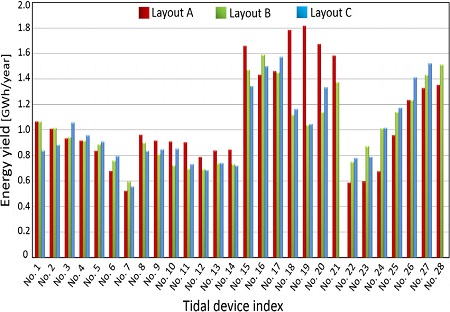
Two measurements to evaluate the energy yield capability of a farm include the net energy (or wake energy yield) of all turbines and the speed-up energy (or gross energy) as shown in Table 4 and Fig. 9. Table 4 expresses the energy yield losses (%) due to wake effects and device installation constraints in three layouts.
This loss is calculated depending on the net energy yield (or wake energy yield) of all turbines in a farm. According to the results in Table 4, it is clearly seen that layout A has the lowest losses (maximum is only about 0.6% at device No. 15). To the contrary, layout B achieves the highest losses (maximum is up to nearly 10% at device No. 18), and all turbines in this farm are affected by the wake flows from the upstream turbines in both tidal directions. In layout C, the biggest losses is found at device No. 9, about 9.7%.
In Fig. 9, layout A shows the highest total gross energy yield for all turbines, about 30.3 GWh/year. Meanwhile, layout C produces the lowest, about 26 GWh/year. In addition, devices No. 15 to 21 in all layouts almost absorb the highest tidal current energy. Conversely, devices No. 6, 7, 22, 23 and 24 show the worst energy generation in all cases, especially devices No. 21 and 28 do not capture the energy yield in layout C. Obviously, all these statistics in Fig. 9 and Table 4 are reasonable and can be explained by the analysis of wake effects and other factors as discussed above.
5. Conclusions
In this paper, three scenarios of tidal stream turbine array inside the Jangjuk-sudo were formulated as an optimization problem constrained by the equation of wake model and the device installation constraints after numerous tests of the device locations, array sizes as well as number of the devices. The following conclusions are given:
- 1) Layout A shows the most impressive performance of tidal current energy extraction, with most the turbines not being much influenced by the upstream turbines' wake effects, and up to 30.3 GWh/year for energy yield.
- 2) Layout C attains the lowest energy yield, namely 13.82% lower than the gross energy yield of layout A. Meanwhile, despite of producing higher energy yield than layout C, all turbines in layout B are decreased in tidal power generation capability due to wake effects from the incident flows of the upstream turbines, about 4.14% energy yield losses due to wake effects.
- 3) Energy yield calculation by means of taking into account the impacts of wake effects, tidal stream device characteristics and device installation constraints, gives more reliable and more accurate results.
Acknowledgments
This research was a part of the project titled “Interaction Study for Optimal Tidal Farm”, funded by the Ministry of Oceans and Fisheries, Korea.
References
-
Esteban, M., and Leary, D., (2012), “Current developments and future prospects of offshore wind and ocean energy”, Applied Energy, Vol. 90(Iss. 1), p128-136.
[https://doi.org/10.1016/j.apenergy.2011.06.011]

- Thyng, K. M., (2012), “Numerical simulation of admiralty inlet, wa, with tidal hydrokinetic turbine siting application”, Ph.D. Dissertation, Department of Mechanical Engineering, University of Washington, US, p22-233.
-
Easton, M. C., Woolf, D. K., and Bowyer, P. A., (2012), “The dynamics of an energetic tidal channel, the pentland firth, scotland”, Continental Shelf Research, Vol. 48, p50-60.
[https://doi.org/10.1016/j.csr.2012.08.009]

-
Ahmadian, R., Falcone, R., and Bockelmann, (2012), “Far-field modelling of the hydro-environmental impact of tidal stream turbines”, Renewable Energy, Vol. 38(Iss. 1), p107-116.
[https://doi.org/10.1016/j.renene.2011.07.005]

-
Hasegawa, Sheng, J., Greenberg, D. A., and Thompson, K. R., (2011), “Far-field effects of tidal energy extraction in the minas passage on tidal circulation in the bay of fundy and gulf of maine using a nested-grid coastal circulation model”, Ocean Dynamics, Vol. 61(Iss. 11), p1845-1868.
[https://doi.org/10.1007/s10236-011-0481-9]

- Sudall, D., Stansby, P., and Stallard, T., (2015), “Energy yield for collocated offshore wind and tidal stream farms”, Proceedings of EWEA Offshore Conference, Denmark.
- Pham, C. T., and Martin, V. A., (2009), “Tidal current turbine demonstration farm in paimpol-bréhat (brittany): tidal characterization and energy yield evaluation with TELEMAC”, Proceedings of the 8th European Wave and Tidal Energy Conference, Sweden.
- Thyng, K. M., and Roc, T., (2013), “Tidal current turbine power capture and impact in an idealized channel simulation”, Proceedings of European Wave and Tidal Energy Conference, Denmark.
-
Funke, S. W., Farrell, P. E., and Piggott, M. D., (2014), “Tidal turbine array optimization using the adjoint approach”, Renewable Energy, Vol. 63, p658-673.
[https://doi.org/10.1016/j.renene.2013.09.031]

- Nguyen, M. H., Jeong, H. C., Kim, J. H., Kim, B. G., and Yang, C. J., (2015), “Evaluation of tidal current energy resource around the southwestern korean peninsula”, Proceedings of the 7th Workshop for Marine Environment and Energy Conference (EAWOMEN), Taiwan.
-
Harrison, M. E., Batten, W. M. J., Myers, L. E., and Bahaj, A. S., (2010), “Comparison between CFD simulations and experiments for predicting the far wake of horizontal axis tidal turbines”, Renewable Power Generation, Vol. 4(Iss. 6), p613-627.
[https://doi.org/10.1049/iet-rpg.2009.0193]

- Bai, L., Spence, R. G., and Dudziak, G., (2009), “Investigation of the influence of array arrangement and spacing on tidal energy converter (TEC) performance using a 3-dimensional CFD model”, Proceedings of the 8th European Wave and Tidal Energy Conference (EWTEC), Sweden.
- Hoang, A. D., Yang, C. J., and Lee, Y. H., (2012), “An evaluation for predicting the far wake of tidal turbines positioned in array at different longitudinal spaces”, Korean Society of Marine Engineering, Vol. 26(Iss. 3), p358-367.
