The Effect of Pump Intake Leaning Angle and Flow Rate on the Internal Flow of Pump Sump
Abstract
Pump sump system or pumping stations are built to draw water from a source such as river and used for irrigation, thermal power plants etc. If pump sump is improperly shaped or sized, air entraining vortices or submerged vortices may develop. This may greatly affect pump operation if vortices grow to an appreciable extent. Moreover, the noise and vibration of the pump can be increased by the remaining of vortices in the pump flow passage. Therefore, the vortices in the pump flow passage have to be reduced for a good performance of pump sump station. In this study, the effect of pump intake leaning angle and flow rate on the pump sump internal flow has been investigated. There are three cases with different leaning angle. Moreover, a pipe type with elbow also has been studied. The flow rate with three classes of air entraining vortices has been examined and investigated by decreasing the water level. The result shows that the air entraining vortices easily occurs at the pump intake with large leaning angle. Moreover, the elbow type of the pump intake easily occurs air entraining vortices at the high flow rate (or velocity) in comparison to other pump intake type.
Keywords:
Internal Flow, Pump Intake Leaning Angle, Pump Sump, Water Level키워드:
내부유동, 펌프 흡입관 설치각도, 펌프 흡수정, 수위1. Introduction
Pump sump system or pumping stations are built to draw water from a source such as river and used for irrigation, thermal power plants etc. If suction sump is improperly shaped or sized, air entraining vortices or submerged vortices may develop. This may greatly affect pump operation if vortices grow to an appreciable extent.(1) Moreover, the noise and vibration of the pump can be increased by the remaining of vortices in the pump flow passage. Therefore, the vortices in the pump flow passage have to be reduced for a good performance of pump sump station.
Many research results can be found for related studies of the pump sump internal flow analysis. Nagura et al.(2) conduct the three dimensional particle tracking velocimetry (3D-PTV) technique to understand the complicated flow inside the suction sump in the vertical-wet-pit-sump configuration. This study successfully found out the suitable condition for the simultaneous measurement with high accuracy. Li et al.(3) studied the three dimensional simulation of flows in practical water pump intakes. This study made significant strides from a simple intake to a real one and shows good prospects of further use of this 3D model to simulate flows in practical water pump intakes. Moreover, Ansar and Nakato(4) studied threedimensional (3D) pump intake flows with and without a cross flow. In their study Acoustic Doppler Velocimetry (ADV) was employed to examine the flow pattern in the approaching flow.
However, the flow in the pump sump is very complicated, even though there is very simple structure of the pump intake. In order to avoid the air entrain into the pump intake to affect pump operation, the characteristics of air entraining by the pump intake pipe leaning angle and flow rate has to be investigated. The previous studies conducted by the fixed water level to investigate the internal flow characteristical of pump sump did not show deeply the relationship between water level and occurrence of the air entrainment. In this study, the air entraining vortices has been examined and investigated by gradually decreasing the water level.
2. Pump Intake Model and Numerical Methods
2.1 Pump intake model
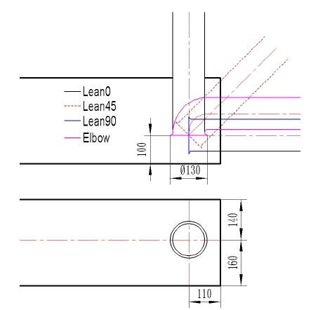
Fig. 1 shows the 2-D view of the pump sump model with different suction pipe types. The pump sump model of TSJ (Turbomachinery Society of Japan)(5) was selected for investigating the effect of suction pipe leaning angle on the pump sump internal flow.
The diameter of the pump intake is D=130 mm. the distance between the inlet bell and floor is C=100 mm. The distance from the rear wall to the pump inlet bell centerline is B=110 mm. The pump inlet bay entrance width is W=300 mm. However, the suction pipe center location is eccentric distribution at the width direction of the pump sump as shown in Fig. 1.
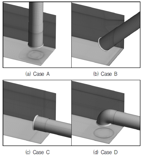
There are 3 leaning angles for the pump intake pipe. The leaning angle of 0˚ is vertical pipe type for Case A. The leaning angle of 45˚ is made for Case B. The pump intake pipe is horizontal arrangement for Case C, for which leaning angle is 90˚. Moreover, there is a pump intake pipe with elbow type as Case D. The pump intake pipe inlet center is kept same for all of cases as shown in Fig. 1. In addition, there are four different outflow rate from Q=0.5 m3/s to Q=1.5 m3/s, applied to different pump intake pipe types as shown in Table 1.
2.2 Numerical methods
For the processing of numerical simulation, a commercial CFD code of ANSYS CFX(6) is adopted. Matsui et al.(7), studied about the numerical simulation on the flow in pump sump with free surface with tetrahedral and hexahedral numerical mesh. According to their study, the tetrahedral numerical mesh can not simulate a smooth water surface. Therefore, the hexahedral numerical meshes of the flow field is applied for each case as shown in Fig. 2. The elements of around 1.3×10⁶ are employed to mesh the fluid domain.
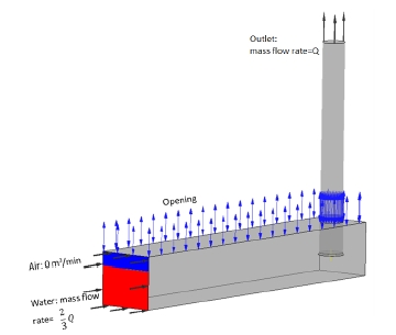
As boundary conditions for the unsteady state calculation the mass flow rate of Q (Table 1) is set for the water flow at the outlet. In order to gradually reduce the water level by the time, the water mass flow rate of and air mass flow rate of 0 are set at inlet. The boundary condition of opening is set at the open duct. The no-slip condition is applied to all of the walls as shown in Fig. 3. Gravity is included for two phase transient calculation. The unsteady state simulation is started from the result of steady state calculation. SST (Shear Stress Transport) turbulence model is used to realize the complicated vortex flow around the pump sump in detail. SST model is two equation turbulence model by Menter et al.(8). Therefore, the turbulence model of SST is adopted in this study.
The CFD method is very important for investigating the flow analysis. The bench marking study for the determined shape of a single pump intake was conducted to acquire the reliability of present CFD analysis method.
The pump sump model of TSJ was selected for the bench marking simulation. Fig. 4 shows the dimension of the TSJ pump sump model. In order to get vortices generated steadily, the center oof pump intake was set no on the centerline of sump.(5) The unsteady state calculation was conducted for the validation test of present CFD analysis method after the 3D modeling and the numerical mesh was established. Table 2 shows the characteristics of CFD codes contributing to establishment of benchmark.
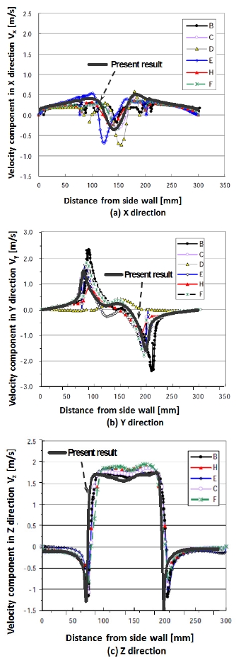
The comparison of present result with the benchmark CFD result is shown in Fig. 5. The comparison result reveals that the velocity component distribution in X, Y and Z directions of present result agrees well with the CFD results by other contributed CFD codes. There is reverse flow in the suction pipe center. The negative velocity occurs at the velocity component in X direction (Vx). The eccentrical whirling flow according to the eccentricity of the suction pipe location is found as shown in Fig. 5 (b).
3. Results and Discussion
3.1 Vortex classification
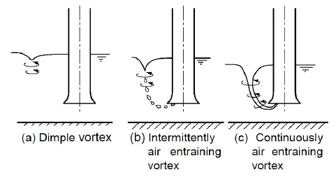
The acceptance criteria of TSJ was applied to estimate the effect of the pump intake leaning angle and flow rate on the internal flow characteristics of pump sump. There are three classification of vortices was applied as shown in Fig. 6.
For the vortex type of class a, Fig. 6 (a), only the dimple vortices are allowed. The surface dimple vortex occurs at the water air interface near suction pipe. For the vortex type of class b, Fig. 6 (b), the dimple vortices and intermittent vortices occurring twice a observing time are allowed. For the vortex type of class c, Fig. 6(c), the dimple vortices and intermittent vortices are allowed. In order to estimate the effect of pump intake leaning angle and flow rate on the internal flow of pump sump, those three acceptance criteria are used.
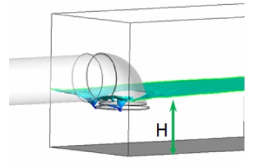
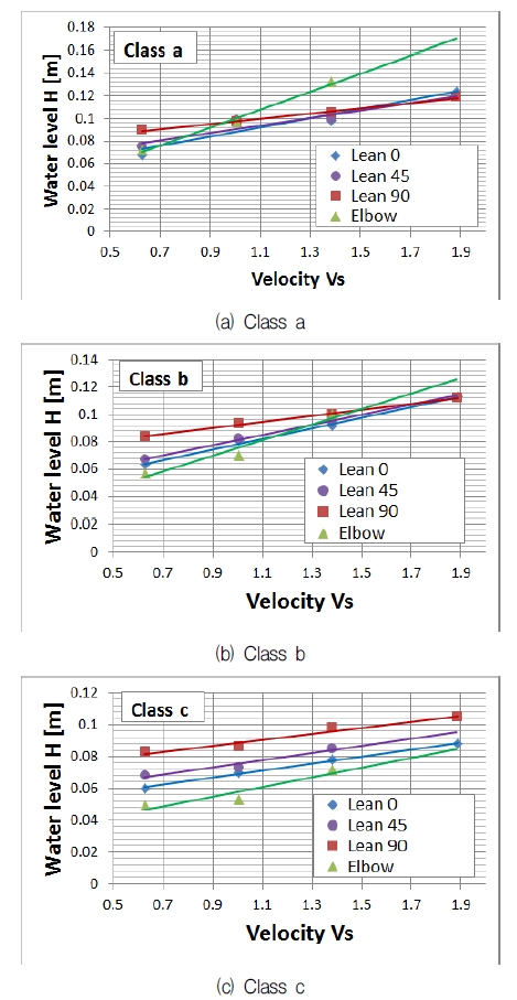
The water level (H) is the height between water air interface and tank floor as shown in Fig. 7. Fig. 8 is shown the results with three criteria. The velocity (vs) at the abscissa is the velocity in the suction pipe, for which definition is shown as follow:
| (1) |
where, the Q is the outflow rate and the unit of the Q is m3/min.
Fig. 8(a) is the relationship between water level height and velocity (Vs) at the condition of the Class a vortex occurring. The water level of elbow pump intake type increases rapidly with increasing the velocity, which means that the pump intake of elbow type easily occurs the Class a vortex in comparison to other pump intake type at high velocity (flow rate) condition.
Fig. 8(b) is the relationship between water level height and velocity (Vs) at the condition of the Class b vortex occurring. The pump intake with large leaning angle easily occurs vortex of Class b at the lowe velocity (flow rate). However, even though the pump intake type is different, there is similar water level when the velocity achieve or larger 1.4 m2/s.
Fig. 8(c) is the relationship between water level height and velocity (Vs) at the condition of the Class c vortex occurring. There is obviously water level by different leaning angle and velocity. With increasing the velocity (flow rate), the slope of the different pump intake type is similar distribution. The water level of large leaning is high, and that of elbow type is the lowest, which means that the large leaning pump intake pipe has the highest risk to occur air entrainment and the elbow type is the safest one.
3.2 Free surface analysis
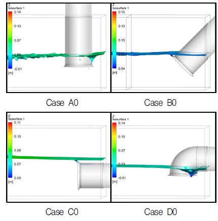
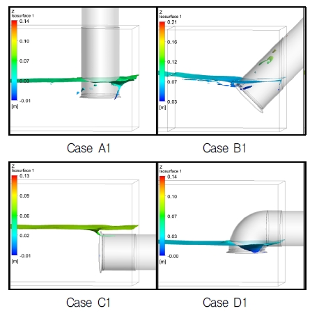
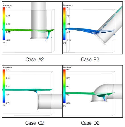
The visualization of free surface is a very important factor to examine the free surface vortex. Moreover, the vortex of Class c has the highest risk for the pump sump system. Therefore, the elevation of free surface with Class c vortex are presented in Figs. 9 to 11. The surface is visualized as a position whose water volume fraction is 0.7. As the water surface keeps moving in the simulation, this is a snapshot at a certain time, which time step is typically for the internal flow analysis.
Fig. 9 to 11 are the free surface flow shape with vortex of Class c at the flow rate from 0.5 m3/s to 1.1 m3/s by the pump intake pipe type, respectively. It can be seen that there is obviously air entrainment near the bell mouth at each case. Moreover, the water level increases with increasing the flow rate from Fig. 9 to 11.
3.3 Velocity component analysis
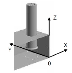
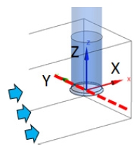
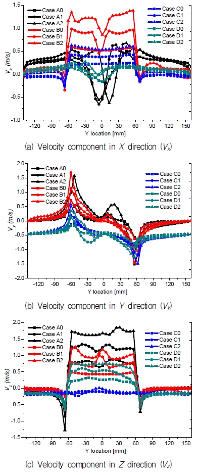
For the purpose of examining the effect of the pump intake leaning angle and flow rate on the pump sump internal flow characteristics in detail, quantitative value of the velocity components distribution at the pump intake is investigated. The vortex of Class c is selected for the velocity component analysis. The measuring location of velocity component is shown in Fig. 12. The coordinate is located at the center of the pump intake. The 0 of the abscissa is the center of the pump intake. The velocity components located on Y axis are plotted in Fig. 13.
Fig. 13(a) shows the velocity component distribution in X direction (Vx). As the bell mouth of Case A and D is vertical, the Vx of those two cases has similar tendency. However, the Vx of Case A has large negative velocity at the center of the bell mouth. Furthermore, there is the highest Vx exists for the pump sump with 45˚ leaning angle pump intake.
Fig. 13(b) presents the velocity component distribution in Y direction (Vy). The Vy of pump sump with 0˚ and 45˚ leaning angle has similar distribution. Moreover, that with 90˚ leaning angle and elbow type has the similar distribution. In general, the Vy of the pump sump with leaning angle smaller than 45˚ is high in comparison to other cases.
Fig. 13(c) indicates the velocity component distribution in Z direction (Vz). There is almost no Vz of the pump sump with 90˚ leaning angle. The velocity component has similar tendency in Z direction by different pump intake type and flow rate.
4. Conclusion
The air entrainment vortices in the TSJ model pump sump is carried out by numerical method. The water level that occurs three classifications of vortex has been examined with reducing the water level gradually.
The pump intake of elbow type easily occurs the Class a vortex in comparison to other pump intake type at high velocity (flow rate) condition. However, elbow type is good at suppressing the Class c vortex. The larger leaning pump intake pipe has the higher risk to occur air entrainment. Especially for the horizontal pump intake, it is relatively the easiest to occurs Class a, b, c vortex at different flow rate in comparison to other different leaning angle.
References
- Japan Association of Agricultural Engineering Enterprise, (1991), Pumping Station Engineering Handbook, Japan.
- Nagura, T., Shintani, A., Kawaguchi, R., Inagaki, K., Maeda, T., and Hirata, K., (2015), “On Measurements of Complicated Flow Structure in a Suction Sump Using the 3D-PTV and the UVP,”, Proceeding of the 13th Asian International Conference on Fluid Machinery, Tokyo, Japan.
- Li, S., Silve, J. M., Lai, Y., Weber, L. J., and Patel, V. C., (2006), “Three-dimensional Simulation of Flows in Practical Water-pump Intakes,”, Journal of Hydroinformatics, 8(2), p111-124.
- Ansar, M., and Nakato, T., (2001), “Experimental Study of 3D Pumpintake Flows with and without Cross Flow,”, Journal of Hydraulic Engineering, 127(10), p825-834.
- Turbomachinery Society of Japan, (2005), Standard Method for Model Testing the Performance of a Pump Sump, TSJ S002.
- ANSYS Inc., (2012), ANSYS CFX Documentation,ver. 13, http://www.ansys.com.
-
Matsui, J., Sugino, Y., and Kawakita, K., (2014), “Numerical Simulation on Flow in Pump Sump with Free Surface,”, In Fluid Machinery and Fluid Engineering, 2014 ISFMFE-6th International Symposium on, p1-5, IET.
[https://doi.org/10.1049/cp.2014.1249]

- Menter, F. R., Kuntz, M., and Langtry, R., (2003), “Ten Years of Industrial Experience with the SST Turbulence Model,”, Turbulence, Heat and Mass Yransfer, 4(1), p625-632.
