Optimization of the Meridional Plane Shape Design Parameters in a Screw Centrifugal Pump Impeller
Abstract
Screw centrifugal pump is a non-clog type pump, which is widely used for drainage and sewage control systems. The screw centrifugal pump combines the advantages of the screw pump and centrifugal pump. Screw centrifugal pump shows the relatively high efficiency and the good solids handing capability. Based on a screw centrifugal pump design method, the parameters of impeller meridional plane shape are investigated for the improvement of pump performance. The design parameters of impeller meridional plane shape, such as impeller inlet and outlet diameters, outlet width, total axial length, blade inlet and outlet angles, and inclination angles, were investigated to examine their effects on the pump performance. Numerical analysis was conducted to determine the essential design variables for the screw centrifugal pump. Furthermore, flow passage shape optimization was conducted to enhance the performance of the screw centrifugal pump.
Keywords:
Screw centrifugal pump, Pump performance, Impeller meridional plane shape, Design parameter, Optimization키워드:
스크류원심펌프, 펌프성능, 임펠러 자오면형상, 설계파라미터, 최적화1. Introduction
Screw centrifugal pump is a special type of pump, which is a combination of a positive displacement pump (screw pump) and a centrifugal pump. The impeller of this pump includes the screw part having the spiral propeller effect as well as the centrifugal part having the centrifugal effect(1). Therefore, the screw centrifugal pump is inherited many advantages from the screw pump and centrifugal pump, such as hydraulic characteristics, solids handling capability, cavitation resistance and high efficiency.
Recently, some topics related to the screw centrifugal pump is available. Kim et al.(2) studied the effect of entrained air in a small screw-type centrifugal pump. The impact of the mean size of bubbles, tip clearances and flow patterns on pump performance was confirmed. Tatebayashi et al.(3) studied the influence of meridional shape on screw-type centrifugal pump performance. The thrust in the screw-type centrifugal pump was investigated by Tatebayashi et al.(4), which showed that the axial thrust became maximum when the impeller radius reached the tongue of the volute casing. Tatebayashi et al.(5) continuously studied the pump performance improvement by restraining back flow in screw-type centrifugal pump. However, the previous study did not show the specific design method of screw centrifugal pump. Cheng et al.(6) studied the parameter equation for the screw centrifugal pump impeller blade and Guo et al.(7) studied the design method and internal flow characteristics of the screw centrifugal pump. These papers are one of the few studies to suggest the clear design method of the screw centrifugal pump impeller. Currently, there is no study to show the optimization of the screw centrifugal pump performance.
In this study, the screw centrifugal pump performance is investigated by changing the design parameters of the impeller meridional plane shape. The Computational Fluid Dynamics (CFD) analysis is conducted to study the effect of the impeller meridional plane shape on the screw centrifugal pump performance. Then, the optimization of the impeller meridional plane shape is performed to improve the pump performance. A numerical code of ANSYS CFX 18.1(8) is applied for all numerical simulations.
2. Design of Screw Centrifugal Pump
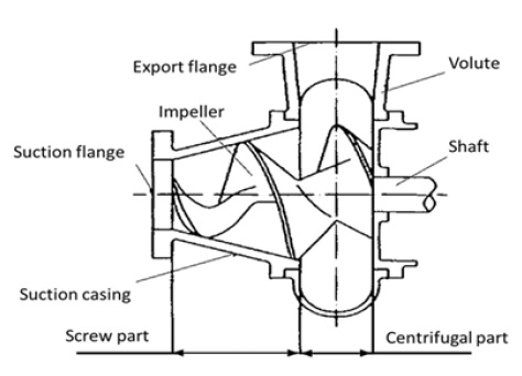
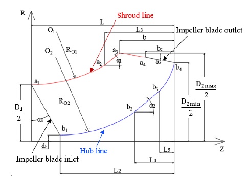
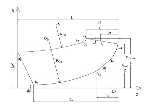
Fig. 1 shows the schematic view of the screw centrifugal pump model(9). The design specification of the screw centrifugal pump model is illustrated in Table 1. The impeller meridional plane shape plays a vital role in screw centrifugal pump performance and is established by the pump parameters, which are calculated by the equations(1,7). The 2D meridional plane shape of the screw centrifugal impeller blade model is shown in Fig. 2. The meridional plane shape consists of the shroud line (a1a2a3a4) including Arc-Line-Line, the hub line (b1b2b3b4) including Arc-Line-Arc, the impeller blade inlet line (a1b1) including a Line, and the impeller blade outlet line (a4b4) including a Line. The design parameters listed in Table 2 are used to established the impeller meridional plane shape of the initial model showed in Fig. 2.
The previous studies(6,7) showed the detailed design method of the screw centrifugal pump impeller, specifically, the spiral profile of the blade. The Z-axis and R-axis are used instead of the x-axis and y-axis, where Z is the axial length and R is the radius. The starting points of shroud line and hub line rotates around the Z-axis with a fixed angular velocity (ωt), and moves along the positive direction of Z-axis at an axial velocity (νt) on the surface (R = f(z)).
The profile equations of shroud line are defined as follows;
| (1) |
| (2) |
| (3) |
The profile equations of hub line are defined as follows;
| (4) |
| (5) |
| (6) |
where θ, Z, R and t represent the wrap angle of impeller blade, the length in the Z-axial direction, the blade radius and the equation variable, respectively, s is the shroud line and h is the hub line.
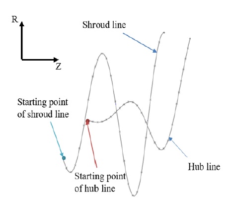
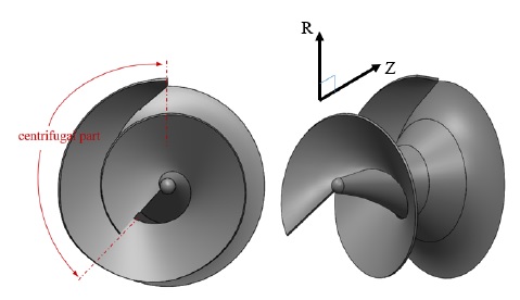
The shroud and hub profiles are drawn according to Eqs. 1 to 6 as shown in Fig. 3. The total wrap angles of the shroud line and hub line are 581° and 583°, respectively, and the total wrap angle of the centrifugal part is 130°. The 3D modeling of the screw centrifugal pump impeller initial model is shown in Fig. 4. The spiral casing of the screw centrifugal pump is designed as the normal centrifugal pump casing design process with the circular shape of casing cross-section(10).
3. Numerical Method
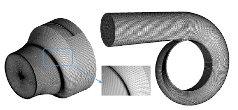
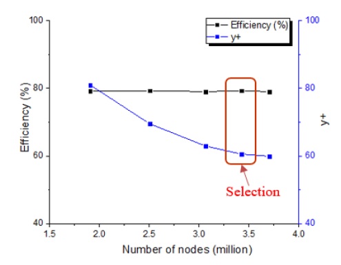
The fluid domain of the screw centrifugal pump geometry was modeled in 3D. CFD analysis was conducted by using a commercial code of ANSYS CFX 18.1. The hexahedral mesh was generated by ANSYS ICEM 18.1(11). Fig. 5 illustrates the numerical grids of impeller and volute casing fluid domains for the pump initial model. Moreover, the mesh dependence test for the pump initial model is implemented as shown in Fig. 6. The mesh dependence test is conducted by investigating the stability of the efficiency and the y+ value calculated by using Eqs. 7 and 8.
| (7) |
| (8) |
where ρ, g, H, Q, τ and ω stand for the density of water, acceleration of gravity, head, flow rate, torque and angular velocity, respectively. y,UT and ν are the absolute distance from the wall, the friction velocity and the kinematic viscosity, respectively.
The structure of the screw centrifugal pump impeller is quite complex, so the y+ value of the impeller was set to 60 at the maximum value. Finally, a mesh number of 3.4 million nodes is selected to conduct the CFD analysis for the screw centrifugal pump model. The information of the numerical grids is shown in detail in Table 3.
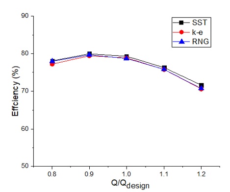
The turbulence models of k-ɛ, RNG k-ɛ, and SST are used to conduct the turbulence model dependence test, and the test results are presented in Fig. 7. As the SST turbulence model is well known for estimating both separation and swirling flow on the wall of complex blade shapes, reasonably, the SST turbulence model is employed for CFD analysis in this study. The whole numerical analysis study was conducted by the Workstation computer with the specifications Intel(R) Xeon(R) CPU E5-2640 0 @ 2.5GHz 2.5GHz (2 processors), 48GB RAM, 64-bit Operating System, x64-based processor for almost 10 weeks.
The numerical method and boundary conditions for steady state analysis are illustrated in Table 4. The mass flow rate and static pressure are set for the inlet and outlet boundary conditions of the pump, respectively. The general connection is set as a frozen rotor between the fixed domain and the rotational domain.
4. Results and Discussion
4.1 Performance curves by a pump initial model
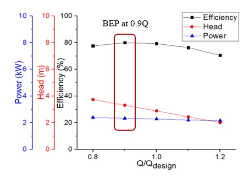
The performance curves by a pump initial model are presented in Fig. 8. The parameters of the initial model shown in Table 2 were selected from the middle value range of the equations referred to(1,7). Therefore, it is conjectured that a few of parameters is not suitable with the specification design and the initial model is quite small that makes the position problem of BEP. So, after the various values of parameters on the impeller meridional plane shape are investigated their impacts on the performance curves, the new parameters are selected for the base model which the BEP matches well with design point (Q/Qdesign = 1.0).
4.2 Effect of impeller meridional plane shapes on the pump performance
The impeller meridional plane shape is determined by the flow rate and effective head of the screw centrifugal pump. The design parameters of the impeller meridional plane shape are the impeller inlet and outlet diameters, blade inlet and outlet angles, outlet width, total axial length, and inclination angles. The variation in the design parameters leads to a change in the impeller meridional plane shape. For the initial model, the parameters change one by one to study their influence on the pump performance. The conditions for the selection of the new parameters are the head and efficiency improvement as well as its BEP position matching with the design point. Table 5 shows the ranges of design parameters to investigate the change in pump performance.
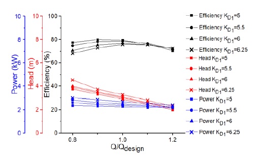
The coefficient of impeller inlet diameter KD1 is used to calculate the inlet diameter of impeller. Design parameter range of the impeller inlet diameter are shown in Table 5. Fig. 9 shows the performance curves of the screw centrifugal pump for various KD1. Fig. 9 indicates that the head at the design point increases with an increase in inlet diameter, but the efficiency decreases accordingly, thus, KD1 = 6 is selected as a base model parameter of the pump performance optimization.
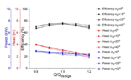
The design variable ranges of the various impeller blade inlet angle α0 and blade outlet angle α3 are illustrated in Table 5. Fig. 10 shows the influence of the impeller blade inlet angle on pump performance. As the impeller blade inlet angle increases from 0° to 42°, at the design point, the value of the pump efficiency increases, and the head decreases.
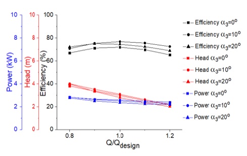
The results of performance curves by the impeller blade outlet angle in Fig. 11 indicate that the case of α3 = 10° is the most efficient compared with the others. Finally, α0 = 25° and α3 = 10° are selected as base model parameters for the optimum design.
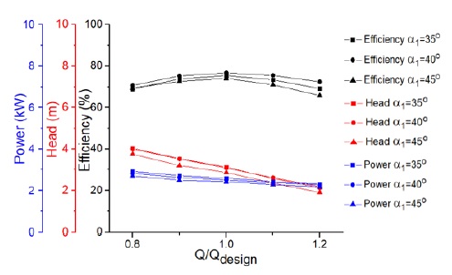
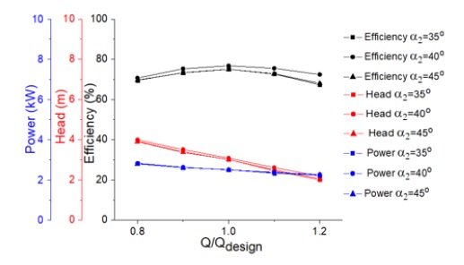
The design variable ranges of impeller blade inclination angles α1 and α2 are shown in Table 5. Three cases of α1and α2 are 35°, 40° and 45°. Figs. 12 and 13 indicate the performance curves by the various α1 and α2. The results by the various α1 and α2 show that α1= 40° and α2 = 40° have the better pump efficiency compared with the others. Therefore, α1= 40° and α2 = 40° are selected as base model parameters.
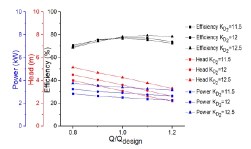
The coefficient of impeller outlet diameter KD2 is used to calculate the outlet diameter of impeller. The design variable ranges of the impeller outlet diameter coefficient are shown in Table 5. Fig. 14 shows the performance curves of the screw centrifugal pump for various KD2. When the impeller outlet diameter increases, the BEP moves to a higher flow rate, for instance, with KD2 = 11.5 and 12, the BEP at the design point, and with KD2 = 12.5, the BEP at 1.1 Qdesign. As the impeller outlet diameter increases, the head increases because the outlet circumferential velocity increases, and eventually, the outlet pressure increases. With KD2 = 12, the head and efficiency are better than case KD2 = 11.5, and the BEP matches well with the design flow rate, whereas KD2 = 12.5, BEP is at 1.1 Qdesign, therefore, KD2 = 12 is selected as a base model parameter.
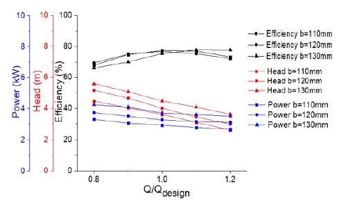
The various impeller outlet widths b from 110mm to 130mm are selected to study the effect of impeller meridional plane shape on the pump performance as shown in Fig. 15. The results implies that the outlet width plays an essential role in the determination of the head of the screw centrifugal pump. At the design point, the increase of the impeller outlet width decreases the pump efficiency and increases the pump head. For the increasing impeller outlet diameter, the BEP moves to the higher flow rate range. b = 120mm is selected as a base model parameter, because the head of case b = 120mm is higher than case b = 110mm, and the BEP is at the design point, whereas case b = 130mm, BEP is at 1.1 Qdesign.
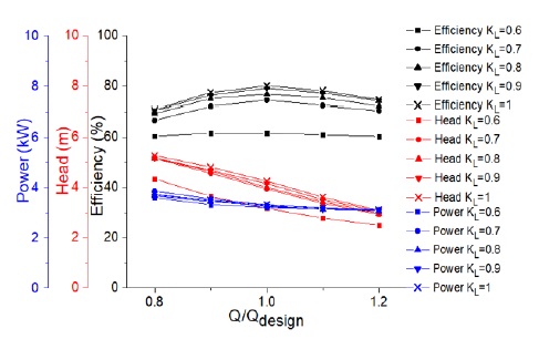
According to the previous study(1,7), the total axial length depends on the impeller outlet diameter. In the industry, this coefficient can be selected more than 1. However, the larger coefficient of total axial length can cause the problem on the pump rotating shaft, so in this study, the various values of the impeller total axial length coefficient KL were selected from 0.6 to 1. Fig. 16 indicates the effect of impeller total axial length on the pump performance. The increase of the impeller total axial length has a remarkable influence on the pump performance, the pump efficiency and head are improved significantly. Therefore, the impeller total axial length is considered as an important design parameters for the screw centrifugal pump. KL = 1 is selected as a base model parameter.
4.3 Optimization process
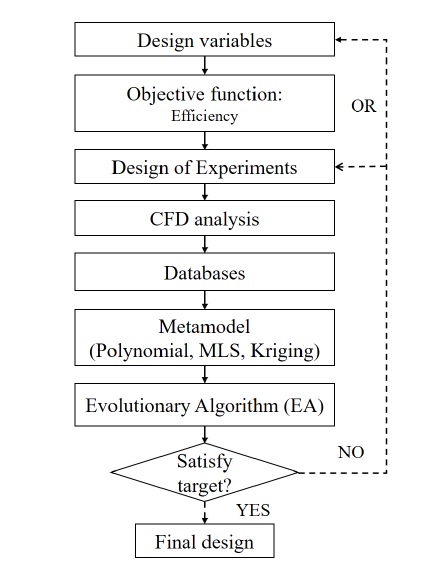
The optimization flowchart for the improvement of the pump efficiency is shown in Fig. 17. According to the parametric study, the best design parameters were selected for the design of the base model. The purpose of optimization is to improve the efficiency of the screw centrifugal pump. The design of experiments (DOE) is created by the orthogonal array method(12) and evaluated by using numerical analysis. The numerical analysis results were used to construct the surrogate model. The surrogate model is used to conduct the optimization by using an Evolutionary Algorithm(13). The optimization procedure is carried out on the commercial software of ANSYS OptiSlang(14).
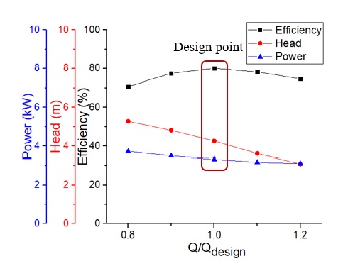
According to the parametric study, the values of parameter are selected to generate the base model. The detailed design parameters of the base model are shown in Table 6. The impeller meridional plane shape and the pump performance curves of the base model are illustrated in Figs. 18 and 19, respectively. The BEP and the design point of the base model match well. The base model is used for the pump efficiency optimization. The parameters, such as impeller inlet diameter, total axial length, inclination angles, and blade inlet angle are selected as design variables to optimize the impeller meridional plane shape. These parameters not only show the effective influence on the pump performance, but also have the BEP location matching well with the design point. Whereas the slightly changing of the impeller outlet diameter, outlet width and blade outlet angle can distort the BEP position. Therefore, three design parameters are fixed in the optimization study.
In this study, the optimization is carried out to improve the hydraulic pump performance, specifically, to maximize efficiency, which is defined as shown in Eq. 7.
Design variables of parameters are selected such as KD1, KL, α0, α1, α2 to make the design of experiments. The orthogonal array method(12) is used to identify the sensitivity of design variables for objective function in this study.
The range of design variables is set as follows;
| (9) |
| (10) |
| (11) |
| (12) |
| (13) |
Table 7 shows DOE created by using the orthogonal array method and their CFD analysis results. The sensitivity analysis is applied to identify the influence of the design variables on the objective function. The sum values of each level for each design variable are defined as Ki and the averaged values are defined as Ki. The value of Ki and Ki are calculated using equations as follows;
| (14) |
| (15) |
where i is the number of the level, j is the number of the design variable, Yij is the value of objective, which corresponds to the design variable j in the level i, Δ is equal to difference between maximum and minimum values of the objective.
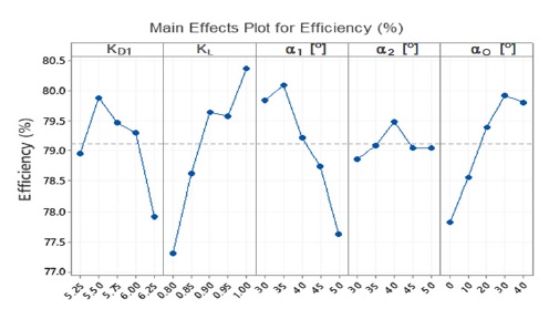
Table 8 and Fig. 20 show the sensitivity analysis of the effect of design parameters on the pump efficiency. According to the sensitivity analysis, KL, α1 [°], α0 [°], KD1 and α2 [°] are arranged from the most sensitive to the least. The total axial length coefficient (KL) is the most important design variable for the pump efficiency improvement.
The surrogate model is prepared by the combination of polynomial regression, moving least square and Kriging. Polynomial regression(15) is a common approximation method where the output response is generally approximated by a polynomial basis function of linear or quadratic order equation with or without coupling terms showed in Eqs. 16 and 17.
| (16) |
| (17) |
where yi is the model output, xi is the input parameter, βi is the coefficient of the equation and an error term εi.
Moving Least Square (MLS)(15) is a local approximation method of the regression as an extension of the polynomial regression. Kriging(13) is the local approximation method that maximize the likelihood function to find optimal parameters. MLS and Kriging are employed to find the approximate relationship between input variables and output target.
The Evolutionary Algorithm(13) is used to conduct the optimization on the impeller meridional plane shape.
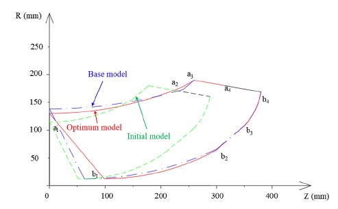
Fig. 21 illustrates the comparison of the impeller meridional plane shapes by the initial, base and optimum models. The comparison of design parameters between the base model and the optimum model is shown in Table 9. The numerical analysis indicated that the efficiency of the optimum model is 82.43% that drops by 0.65% compared with the optimal model predicted by surrogate model.
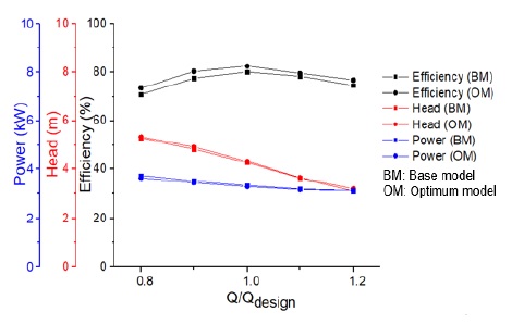
Fig. 22 indicates that the efficiency of the optimum model is higher than the base model at a wide operating range. At the design point, the efficiency of the optimum model is increased by 2.35%.
5. Conclusions
The aim of this study is focused on the optimization of the impeller meridional plane shape design parameters of a screw centrifugal pump to improve the pump performance, especially the pump efficiency.
The total process of the pump efficiency optimization is figured out and conducted to investigate the effect of the various impeller meridional plane shape design parameters of the screw centrifugal pump on the pump performance as follows;
- 1. Design method establishment based on the blade profile equations.
- 2. Initial model determination for the design method verification.
- 3. Base model determination to match the design specification.
- 4. Optimum model determination to improve the pump efficiency.
The initial model is used to investigate the design parameters, which include the impeller inlet and outlet diameters, blade inlet and outlet angles, outlet width, total axial length, and inclination angles. From the investigation of the design parameters of the initial model, reasonable values of the parameters are selected to generate the base model which has the pump performance matching well with the design specification. The base model is applied for the optimum design to improve the pump efficiency.
The study results show that the impeller outlet diameter and total axial length are confirmed as the most important parameters among the investigated parameters to improve the pump performance. The pump efficiency of the optimum model is 82.43% at the design point, which is 2.35% higher than the base model.
References
- Guan, X. F., 2011, Modern pump theory and design, China Astronaut, Beijing, China (in Chinese).
- Kim, Y., Tanaka, K., Lee, Y., Matsumoto, Y., 1999, “Effects of entrained air on the characteristics of a small screw-type centrifugal pump”, The KSFM Journal of Fluid Machinery, Vol. 2, No. 3, pp. 37∼44.
-
Tatebayashi, Y., Tanaka, K., 2002 “Influence of meridional shape on screw-type centrifugal pump performance”. Proc. of ASME Fluids Engineering Division Summer Meeting, FEDSM2002-31183, pp. 769∼776, Canada.
[https://doi.org/10.1115/FEDSM2002-31183]

- Tatebayashi, Y., Tanaka, K., Kobayashi, T., 2003, “Thrust prediction in screw-type centrifugal pump”. Proc. of 4th ASME_JSME Joint Fluid Engineering Conference, FEDSM2003-45105, pp. 621∼626, Hawaii, USA.
-
Tatebayashi, Y., Tanaka, K., Kobayashi, T., 2005 “Pump performance improvement by restraining back flow in screw-type centrifugal pump”. ASME Journal of Turbomachinery, pp. 755∼762, Houston, TX, USA.
[https://doi.org/10.1115/1.2019217]

-
Cheng, X., Lia, R., 2012, “Parameter equation study for screw centrifugal pump”. Procedia Engineering, Vol. 31, pp. 914∼921.
[https://doi.org/10.1016/j.proeng.2012.01.1121]

-
Guo, M., Choi, Y. D., 2017, “Design and CFD analysis of a screw centrifugal pump model”. Journal of the Korean Society of Marine Engineering, Vol 43, No. 8, pp. 640∼647.
[https://doi.org/10.5916/jkosme.2019.43.8.640]

- ANSYS Inc, ANSYS CFX Documentation, Ver. 18.1, http://www.ansys.com, , Accessed, 2018.
- Min, Z., Zhu, D, K., Han, W., Zhang, Z. H., Li, Z. Y., 2012, “Improvement of hydraulic design method for screw centrifugal pump impeller based on auxiliary lines”. Journal of Lanzhou University of Technology, Vol. 38, No. 2, pp. 47∼50 (in Chinese).
- Stepanoff, A. J., 1957, Centrifugal and Axial Flow Pumps: Theory, Design, and Application, 2nd edition, John Wiley & Sons, Inc.
- ANSYS ICEM., ANSYS ICEM Documentation, Ver. 18.1, http://www.ansys.com, , Accessed, 2018.
- Taguchi, G., Wu, Y., 1985, Introduction to off-line quality control, Central Japan Quality Control Association, Tokyo.
-
Kim, K. Y., Samad, A., Benini, E., 2019, Design Optimization of Fluid Machinery: Applying Computational Fluid Dynamics and Numerical Optimization, John Wiley & Sons Singapore Pte. Ltd.
[https://doi.org/10.1002/9781119188377]

- ANSYS OptiSLang., ANSYS optiSLang Doc., Ver. 18.1, http://www.ansys.com, , Accessed, 2018.
- Most, T., Will, J., 2011, “Sensitivity analysis using the Metamodel of Optimal Prognosis”, Weimar Optimization and Stochastic Days, 8, pp. 24∼40.
