Hydraulic and Suction Performances of the Screw Centrifugal Pump for Live Fish Transfer According to Impeller Blade Inlet Shapes
Abstract
A screw centrifugal pump is a non-clog type pump known as the sewage pump to transfer solids such as rags, hair, clusters of stringy material, and digested sludge applications. With the large and open channel from suction to discharge, the screw centrifugal pump shows better solids transferring capability, even the sensitive products such as food (tomato, potato), live fish, eel, shrimp. However, the impeller blade inlet of screw centrifugal pump with the high rotation speed can damage the live fish or food. Therefore, in this study, the impeller blade inlet shapes are investigated for their influence on the performance of the live fish transfer pump. The straight, concave, and convex blade inlet shapes are created. Numerical analysis was conducted to study the pump hydraulic and suction performances according to the impeller blade inlet shapes of the screw centrifugal pump.
Keywords:
Screw centrifugal pump, Impeller blade inlet shape, Live fish transfer, Hydraulic performance, Suction performance키워드:
스크류원심펌프, 임펠러 블레이드 입구 형상, 활어 이송, 수력성능, 흡입성능1. Introduction
The screw centrifugal pump is widely used in industry to transfer sewage or sensitive foods such as tomato, potato, live fish, eel, shrimp, etc. With the large and open channel from suction to discharge, the screw centrifugal pump is preferable to transfer the solids without clogging. The screw centrifugal pump impeller includes the screw part with the spiral propeller effect and the centrifugal part with the centrifugal effect [1]. A screw centrifugal pump combines the advantages of a screw pump and centrifugal pump, such as no blockage, higher efficiency, wider high-efficiency area, cavitation, etc. However, the major disadvantage of a screw centrifugal pump is the injury and damage of the sensitive food by the blade inlet shape. The unsuitable blade inlet shape can cut or damage the live fish body as injuries, descaling, and bruising.
There are few studies about the impeller blade inlet shape or the fish transferring application of a screw centrifugal pump. There are just some topics related to the screw centrifugal pump. Kim et al. [2] studied the effect of entrained air in a small screw-type centrifugal pump and confirmed the impact of the mean size of bubbles, tip clearances, and flow patterns on pump performance. Tatebayashi et al. [3] studied the influence of meridional shape on screw-type centrifugal pump performance. The thrust in the screw-type centrifugal pump was investigated by Tatebayashi et al. [4], which showed the axial thrust became maximum when the impeller radius reached the tongue of the volute casing. Tatebayashi et al. [5] also studied the pump performance improvement by restraining backflow in a screw-type centrifugal pump. Cheng et al. [6] explained the parameter equation for the screw centrifugal pump impeller blade, and Guo et al. [7] studied the design method and internal flow characteristics of the screw centrifugal pump.
In the industry, a screw centrifugal pump was researched and used as the live fish pump, and the experimental results [8, 9] of the fish pump showed the damage and injuries of fish still existed. Therefore, this study is aimed to investigate the influence of the impeller blade inlet shape of screw centrifugal pump on pump hydraulic and suction performances for friendly fish transfer.
2. Design and modeling of screw centrifugal pump model for the fish transfer
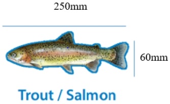
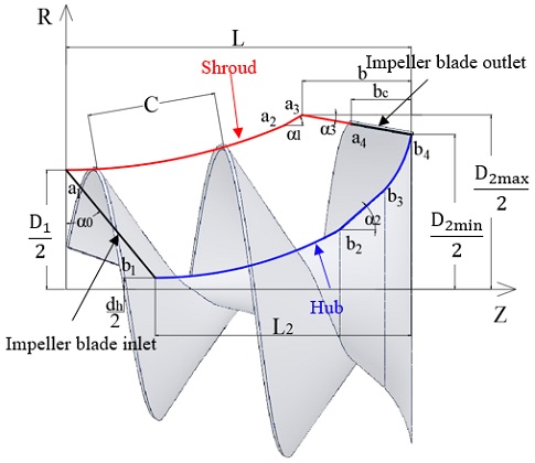
The design specification of the screw centrifugal pump model is illustrated in Table 1. Selecting a screw centrifugal pump with rotational speed is low as 650 min-1 to friendly transfer the fish. The impeller plays a vital role in the screw centrifugal pump. An impeller for a screw centrifugal pump was designed from previous studies [1, 7]. The target fish species in this study are trout or salmon, and the fish size shown in Fig. 1 is the length of 250 mm and the width of 60 mm with a maximum weight of 0.7 kg. The design parameters of the meridional plane shape of the screw centrifugal pump impeller are shown in Table 2. Fig. 2 showed the impeller meridional plane shape with a straight inlet shape. According to the impeller design parameters, the impeller channel width can be adjusted to have enough space to transfer the fish.
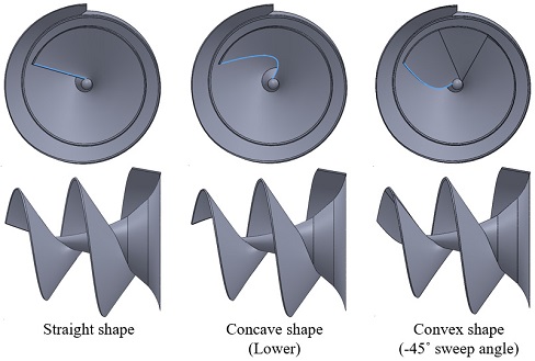
The blade inlet shape is an essential part of the screw centrifugal pump impeller because it affects the safety of the transferring live fish such as trout, salmon, eel, shrimp, etc. Therefore, the study of impeller blade inlet shape of screw centrifugal pump is necessary. Fig. 3 shows three initial types of blade inlet shapes considered to use in this study are the straight, concave, and convex shapes. Bezier curve is used to design the initial concave and convex blade shapes. The impeller was designed with the same meridional plane shape but a change in the blade inlet shapes.
2.1 Concave shape design
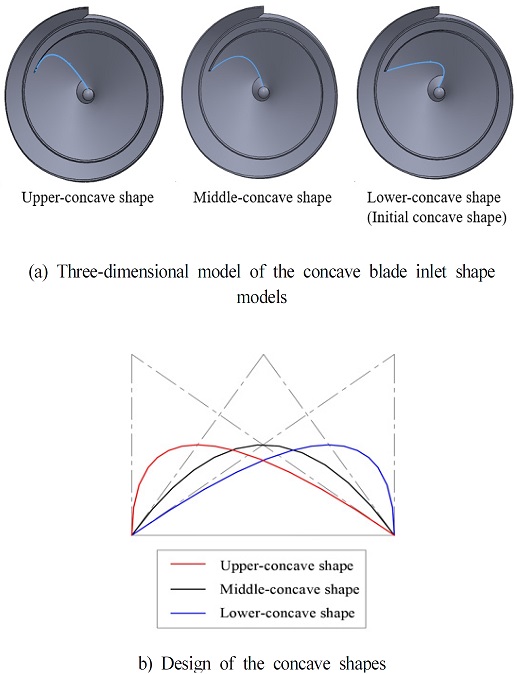
Besides the initial concave inlet shape model shown in Fig. 3, called lower-concave shape, two more types of the concave inlet shape are generated as the upper concave and middle concave shapes shown in Fig. 4. The concave shapes are established by the Bezier curve [10] as the following equation.
| (1) |
where P0, P1, P2 are the control points of the quadratic Bezier curve. P0, P1 are the end points, P2 is the middle point.
2.2 Convex shape design
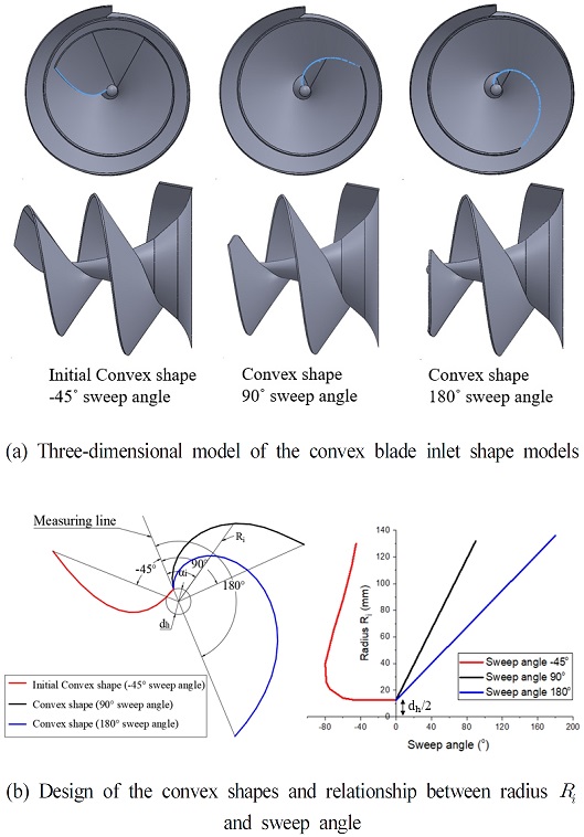
The initial convex inlet shape model shown in Fig. 3 is established by the Bezier curve. However, two more types of convex inlet shape with 90° and 180° sweep angles are generated using Eq. (2). Fig. 5(b) presents the design of the convex blade inlet shapes. The convex shapes with 90° and 180° sweep angles are designed by the proportion formula as;
| (2) |
where αf and Rf are the total sweep angle and radius at the end point (αf = 90°; 180°), αi and Ri are the sweep angle and radius at the point i.
3. Numerical method
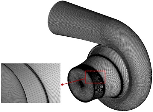
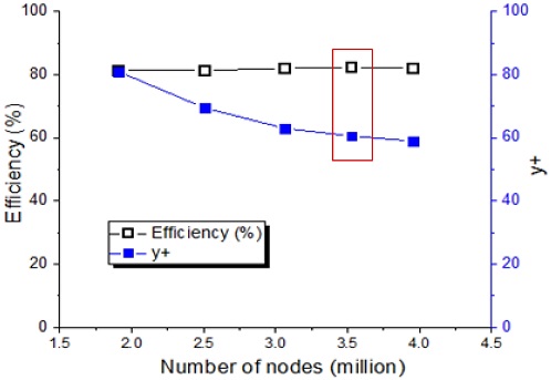
The fluid domain of the screw centrifugal pump geometry was modeled in 3D. CFD analysis was conducted by using a commercial code of ANSYS CFX 18.1 [11]. ANSYS ICEM 18.1 [12] is used to generate the structured mesh for numerical analysis. Fig. 6 illustrates the numerical grids of impeller and volute casing fluid domains for the pump model with the straight impeller blade inlet shape. Efficiency and y+ value are selected to evaluate the mesh dependency test. Fig. 7 shows the mesh dependence test, which indicates the selected 3.5 million mesh number for numerical analysis. Table 3 indicates the discretization error [13] for the numerical method is less than 1%. Therefore, the numerical methodology for screw centrifugal pumps is acceptable.
| (3) |
| (4) |
where ρ, g, H, Q, τ and ω stand for the density of water, acceleration of gravity, head, flow rate, torque and angular velocity, respectively. y, UT and ν are the absolute distance from the wall, the friction velocity and the kinematic viscosity, respectively, r is refinement factor between the coarse and fine grid, ϕ1 is efficiency, ϕ2 is head in (m), ϕ3 is power in (kW). p is formal order of accuracy of the algorithm, ϵ32=ϕ3-ϕ2, ϵ21=ϕ2-ϕ1, is approximate relative error, is extrapolated relative error, is fine-grid convergence index [13].
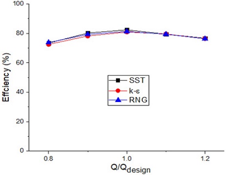
Fig. 8 presents the turbulence model dependence test with the k-ɛ, RNG k-ɛ, and SST turbulence models. The adopted three turbulence models confirm well the efficiency characteristics of the pump. The SST turbulence model was employed for the CFD analysis in this study because it evaluates the complex flow field in fluid machinery [14].
The numerical method and boundary conditions are illustrated in Table 4. The frozen rotor was selected to reduce the simulation time and pass actual flow downstream. For the cavitation flow simulation, The Rayleigh-Plesset model is adopted to evaluate the cavitation. The total pressure of the inlet with zero reference pressure and mass flow rate of the outlet is selected as the boundary conditions of the pump. The development of cavitation occurrence is easily controlled by adjusting the inlet pressure. The general connection is set as a frozen rotor between the fixed domain and the rotational domain.
4. Results and discussion
4.1 Pump hydraulic performance
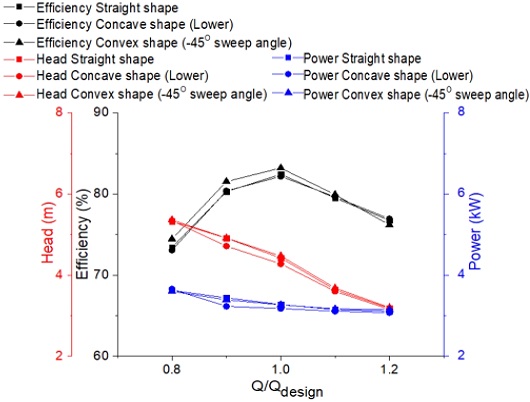
The pump performance for the three initial types of blade inlet shape model under the non-cavitation condition from the computational simulation is shown in Fig. 9. The results show that the efficiency and head of the convex blade inlet shape model are higher than the straight and concave blade inlet shape models at the design point. At the higher flow rates, three-blade inlet shape models have nearly the same non-cavitating hydraulic performance.
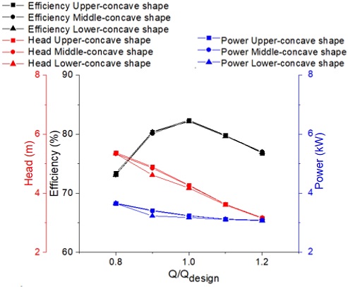
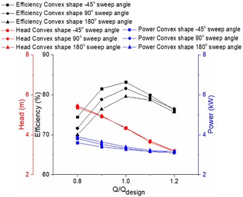
A comparison of pump performance of three concave inlet shape models is shown in Fig. 10. The efficiency of the three concave inlet shape models is almost the same. The efficiency and head of the Upper-concave shape model are slightly higher than those of the Middle-concave shape model, and the efficiency and head of the Middle-concave shape model are higher than those of the Lower-concave shape model. Fig. 11 shows the pump performance curves of screw centrifugal pump models with three different convex inlet shapes. The head of three convex inlet shape models is relatively similar. The efficiency of the initial convex shape model with the -45° sweep angle is higher than those of the 90° and 180° sweep angle convex shape models.
4.2 Loss analysis
The loss analysis in the impeller and volute is conducted using the following equations:
| (5) |
| (6) |
where hloss-impeller gives the total loss for the pump impeller, hloss-volute gives the total loss for the pump volute, ∆pt is the total pressure difference in the respective components of the pump.
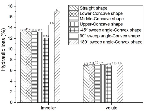
Fig. 12 presents the loss analysis of the impeller and volute in the different blade inlet shape models at the design condition. In the volute domain, the hydraulic loss of all the models is similar. In the impeller domain, the hydraulic loss of the straight shape model and three types of concave shape models has no significant difference. The hydraulic loss of the initial convex shape model with the -45° sweep angle is lowest, and the loss of the 180° sweep angle convex shape is highest. Therefore, the efficiency of the initial convex shape model is highest, but the 180° sweep angle convex shape model shows the lowest efficiency.
4.3 Internal flow characteristics
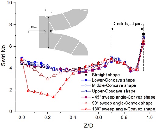
The development of swirl flow relates to the damage of fish while passing through the pump impeller. The swirl number is adopted to evaluate the effect of blade inlet shape effect. The swirl number is calculated at the various locations along the impeller passage. The swirl number [15] is defined as Eq. (8) below:
| (7) |
where Vθ and VZ are the velocity components in the circumferential and axial directions, r and R are the local and full radius, respectively, at each Z/D location shown in Fig. 13.
Fig. 13 presents the swirl number distribution of all screw centrifugal pump models with the different impeller blade inlet shapes at the design condition. The values 0.0 and 1.0 of Z/D mean the axial locations at the impeller inlet and hub outlet, respectively. The swirl number distribution is similar in all blade inlet models except for the 90° and 180° sweep angle convex shape models.
It is conjectured that the 180° sweep angle convex shape consumes more power to reach the design head at the design flow rate, which contributes to the hydraulic loss in the impeller with the relatively higher sweep angle convex blade shape. The swirl number at the inlet of the 180° sweep angle convex blade shape is comparatively lower than the other inlet shapes because of the smooth change of the blade inlet sweep angle. The 180° sweep angle convex impeller inlet shape model showed a lower swirl number, which implies superior internal flow condition among the designed impeller inlet shapes for the fish transfer.
The distribution of velocity streamlines at 1.0 Qdesign is presented in Fig. 14. As seen from the figure, the swirl flow can be seen near the impeller hub in all the screw centrifugal impeller models. However, in the case of the 180° sweep angle convex shape model, the streamline near the impeller hub cone is relatively more uniform than the others. However, a minor recirculation region is found near the inlet of the impeller shroud. It is conjectured that the different flow tendency near the impeller inlet results from the different impeller blade inlet shapes. According to the internal flow investigation, it is concluded that cutting the tip of the impeller blade inlet shows that impeller inlet flow can flow more uniformly and smoothly without clogging, and there exists a small swirl flow near the blade tip. Therefore, the reduced blade inlet area with the larger sweep angle convex shape is convenient for fish to enter the pump impeller.
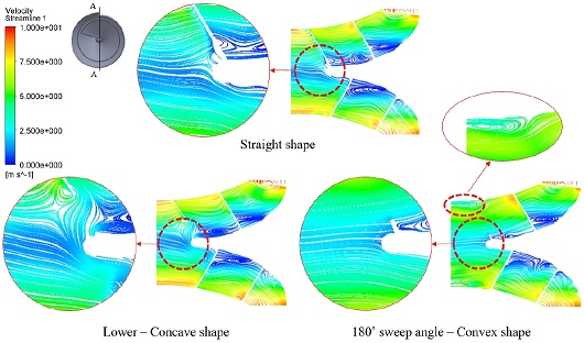
Velocity streamline of screw centrifugal pump models with the different blade inlet shapes at 1.0 Qdesign (A-A cross section)
Fig. 15 illustrates the pressure contour of the screw centrifugal pump with various convex blade inlet shapes both on the suction and pressure sides. Both the suction and pressure sides of the impeller blade are observed by the front view. As the blade sweep angle changes, the pressure contour distribution on the pressure side is relatively similar, but the pressure contours on the suction side change according to the sweep angle. The area of the low-pressure zone gradually increases when increasing the sweep angle, however insignificantly.
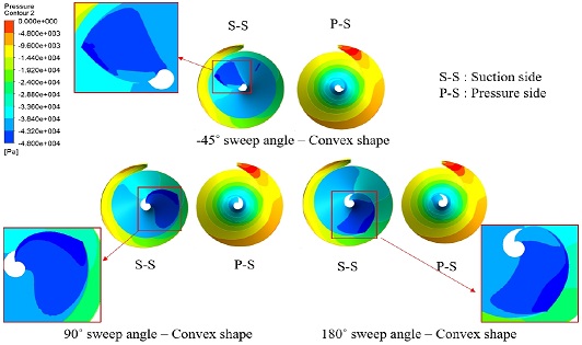
Pressure distribution of screw centrifugal pump models with three different convex blade inlet shapes at 1.0 Qdesign
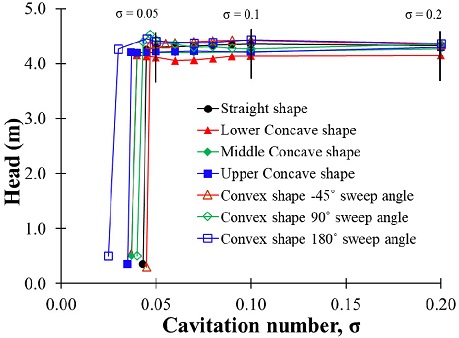
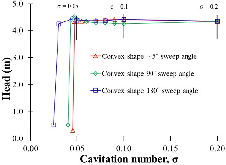
Fig. 16 shows the suction performance comparison in screw centrifugal pump models with various blade inlet shapes by CFD analysis. The definition of the cavitation coefficient (σ) [16] is shown as Eq. (9).
4.4 Pump suction performance
| (8) |
where NPSH is net positive suction head, p0 is the pump inlet pressure, pv is the saturated vapor pressure and H is the effective head.
For the cavitation analysis, the inlet pressure reduced as the cavitation number decreased. Fig. 16 presents the suction performance by the blade inlet shapes. The result indicates that the suction performance of the convex blade inlet shape with 180° sweep angle is better than the other blade inlet shape models. The phenomena of cavitation occurrence in the screw centrifugal pump model having the screw impeller structure are similar to that in the inducer structure. It is interesting to confirm the extension of the cavitation coefficient number to the lower region by the increased blade sweep angle. Similar results can be seen in the inducer by the studies of Kang et al. [17] and Ashihara et al. [18] with a change in the blade inlet sweep angle. To compare the relationship between the impeller blade inlet shape and suction performance, suction performance and vapor volume fraction at the different cavitation coefficients by all the blade inlet shape models were examined in detail in the following section.
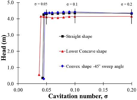
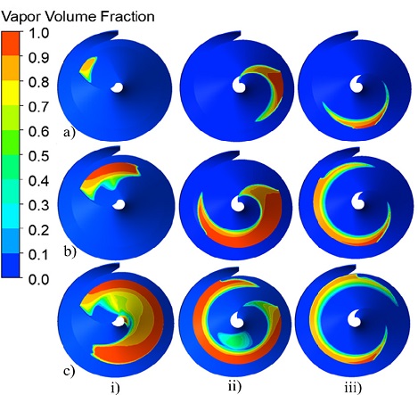
Figs. 17 and 18 present the suction performance and the vapor volume fraction contours of the three initial blade inlet shapes at the different cavitation coefficient numbers.
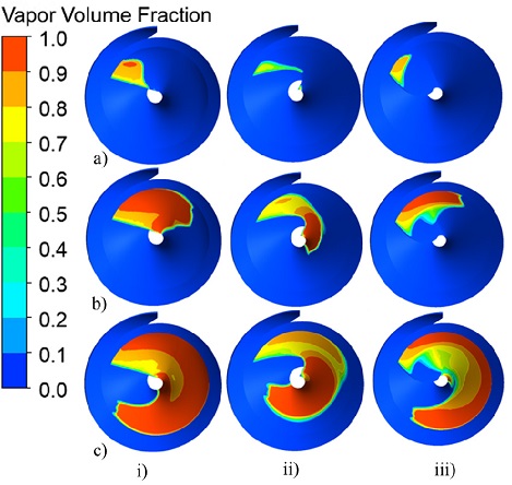
Vapor volume fraction distribution on suction surface of i) straight ii) lower concave and iii) -45° sweep angle convex blade shapes at σ = a) 0.2, b) 0.1 and c) 0.05
The vapor volume fraction is shown at various cavitation coefficients: σ=0.2, σ=0.1 and σ=0.05. The cavitation analysis results for the initial blade inlet shapes showed a lower concave blade than the straight and initial convex shape models. Moreover, the lower concave shape also shows the smallest vapor volume area among three initial blade shape models in all cavitation stages, in which 0 means water and 1 means water vapor.
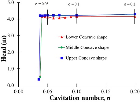
Figs. 19 and 20 show the results of the cavitation analysis for the three types of concave blade inlet shape models include the suction performance and the vapor volume fraction distribution, respectively. For the concave blade inlet shape models, the higher volume fraction area is located near the hub of the blade inlet, and the vapor volume fraction increases as the cavitation coefficient decrease. The suction performance of all the concave shape models is relatively similar, just like the similar tendencies that hydroelectric performance has shown.
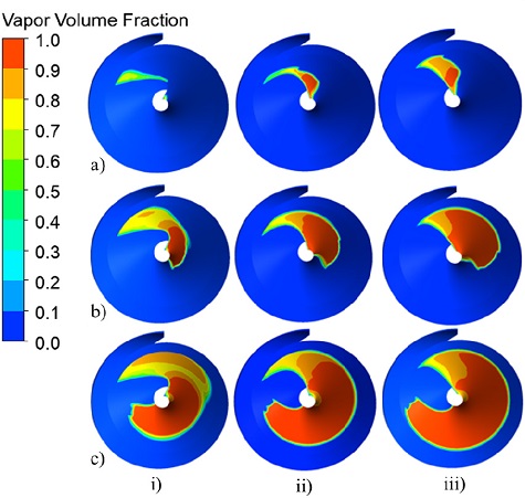
Vapor volume fraction distribution on suction surface of i) lower ii) middle and iii) upper concave blade shapes at σ = a) 0.2, b) 0.1 and c) 0.05
For the cavitation analysis of three types of the convex blade shape models, Figs. 21 and 22 showed the suction performance and the vapor volume fraction distribution of three various impeller blade inlet convex shapes. The 180° sweep angle convex shape model shows better suction performance than the 90° and –45° sweep angle convex shape models. The cavitation inception occurs at the blade tip on the suction surface of the convex inlet shape models. At the cavitation coefficient numbers of and, the 180° sweep angle convex blade inlet shape model has the better vapor volume fraction distribution than the 90° sweep angle convex blade inlet shape and –45° sweep angle convex shape models. Therefore, the examined results indicate that the convex blade inlet shape with a larger sweep angle suppresses the cavitation instabilities more efficiently.
It is concluded that the 180° sweep angle convex blade inlet shape shows the best suction performance among all the adopted blade inlet shape models.
5. Conclusions
The influence of impeller blade inlet shape on the hydraulic and suction performances of the screw centrifugal pump for live fish transfer was investigated by CFD analysis. The transportation of fish is affected by the cavitation in the pump. The suppression of cavitation is required for the transfer of fish without any damage. Therefore, the screw centrifugal pump should maintain the suction pressure above vapor pressure during operation to avoid cavitation and safe fish transfer.
The results indicate that the pump hydraulic efficiency of the initial convex blade inlet shape model, which has a relatively low blade sweep angle, is the best under the non-cavitating condition. The 180° sweep angle convex blade inlet shape model shows better suction performance than the other models. Although the 180° sweep angle convex blade inlet shape model has a relatively lower pump hydraulic efficiency in comparison with the other convex blade inlet shapes, this blade inlet shape results in relatively smooth and uniform flow patterns, as well as the superior cavitation suppression ability in the impeller passage.
Therefore, the findings in this study conclude that the selection of convex blade inlet shape with suitable sweep angle in consideration with the trade-off between the pump hydraulic and suction performances is preferable for live fish transfer.
References
- Guan, X. F., 2011, Modern pump theory and design, China Astronaut, Beijing, China (in Chinese).
- Kim, Y., Tanaka, K., Lee, Y., Matsumoto, Y., 1999, “Effects of entrained air on the characteristics of a small screw-type centrifugal pump”, The KSFM Journal of Fluid Machinery, Vol. 2, No. 3, pp. 37-44.
-
Tatebayashi, Y., Tanaka, K., 2002 “Influence of meridional shape on screw-type centrifugal pump performance”, Proc. of ASME Fluids Engineering Division Summer Meeting, FEDSM2002-31183, pp. 769-776, Canada.
[https://doi.org/10.1115/FEDSM2002-31183]

- Tatebayashi, Y., Tanaka, K., Kobayashi, T., 2003, “Thrust prediction in screw-type centrifugal pump”, Proc. of 4th ASME_JSME Joint Fluid Engineering Conference, FEDSM 2003-45105, pp. 621-626, Hawaii, USA.
-
Tatebayashi, Y., Tanaka, K., Kobayashi, T., 2005 “Pump performance improvement by restraining back flow in screw-type centrifugal pump”, ASME Journal of Turbomachinery, pp. 755-762, Houston, TX, USA.
[https://doi.org/10.1115/1.2019217]

-
Cheng, X., Lia, R., 2012, “Parameter equation study for screw centrifugal pump”, Procedia Engineering, Vol. 31, pp. 914-921.
[https://doi.org/10.1016/j.proeng.2012.01.1121]

-
Guo, M., Choi, Y. D., 2017, “Design and CFD analysis of a screw centrifugal pump model”, Journal of the Korean Society of Marine Engineering, Vol 43, No. 8, pp. 640-647.
[https://doi.org/10.5916/jkosme.2019.43.8.640]

- Jackson, D., 2014, “Implications Of The Eel Regulations On The Design Of A Pumping Plant”, WIT Transactions on State-of-the-art in Science and Engineering, Vol. 71, pp. 10.
- Helfrich, L. A., Bark, R. C., Liston, C. R., Mefford, B. W., 2003, “Survival and condition of striped bass, steelhead, delta smelt, and wakasagi passed through a Hidrostal pump at the Tracy Fish Collection Facility”.
- Mortenson, M. E., 1999, Mathematics for computer graphics applications, 2nd edition, Industrial Press Inc., New York.
- ANSYS Inc, ANSYS CFX Documentation, Ver. 18.1, http://www.ansys.com, , Accessed, 2018.
- ANSYS ICEM., ANSYS ICEM Documentation, Ver. 18.1, http://www.ansys.com, , Accessed, 2018.
-
Celik, I. B., Ghia, U., Roache, P.J., Freitas, C.J., Coleman, H., Raad, P.E., 2008, “Procedure for Estimation and Reporting of Uncertainty Due to Discretization in CFD Applications”, ASME. J. Fluids Eng., Vol. 130, 078001.
[https://doi.org/10.1115/1.2960953]

- Menter, F. R., Kuntz, M., Langtry, R., 2003, “Ten Years of Industrial Experience with the SST Turbulence Model”, Proc. of the 4th International Symposium on Turbulence, Heat and Mass Transfer, Begell House Inc., West Redding, pp. 625-632.
-
Sheen, H. J., Chen, W. J., Jeng, S. Y. and Huang, T. L., 1996, “Correlation of swirl number for a radial type swirl generator”, Experimental Thermal anf Fluid Science, Vol. 12, pp. 444-451.
[https://doi.org/10.1016/0894-1777(95)00135-2]

- Brennen, C. E., 2011, Hydrodynamics of Pumps, Cambridge University Press.
-
Kang, D. H., Watanabe, T., Yonezawa, K., Horiguchi, H., Kawata, Y., Tsujimoto, Y., 2009, “Inducer design to avoid cavitation instabilities”, International Journal of Fluid Machinery and Systems, Vol. 2, No. 4, pp. 439-448.
[https://doi.org/10.5293/IJFMS.2009.2.4.439]

-
Ashihara, K., Goto, A., 2002, “Effects of Blade Loading on Pump Inducer Performance and Flow Fields”, Proceedings of the ASME 2002 Joint U.S.-European Fluids Engineering Division Conference FEDSM2002-31201, Vol 2, pp. 925-934, Canada.
[https://doi.org/10.1115/FEDSM2002-31201]


