A Feasibility Study on the Flow Passage Shape for an Inline Francis Hydro Turbine
Abstract
The aim of this study is to investigate the feasibility of a new type of casing for the inline Francis hydro turbine. Comparing with the traditional turbine with spiral casing, this turbine is unique for its flow passage shape at the first stage of flow to the turbine, very similar to a pipe, called inline casing. Before the commercialization of this new type of casing, a global investigation of the inline casing must be conducted. Preserving the structural characteristics of simple, compact-size and convenient for manufacture, different shapes of the belt passage, vertical corner and stay vanes are applied to investigate the influence of flow passage shape on the turbine performance. Stable and relatively high efficiency is achieved regardless of flow passage shape difference proving the feasibility of the inline casing used in a hydro turbine.
Keywords:
Inline casing, Feasibility study, Flow passage shape, Performance키워드:
인라인 케이싱, 타당성 연구, 유로 형상, 성능1. Introduction
The Francis turbine is a type of water turbine that was developed by James B. Francis in 1848 (1). Since then, the Francis turbine has been designed with a spiral casing as a mandatory component. The function of the spiral casing is to convert the pressure energy of the working fluid into momentum energy just before the fluid enters the runner.
With rapid economical development, more and more attention is paid to space utilization, the design of Francis turbine structure is also moving towards a simpler structure and more compact size. The traditional Francis turbine with spiral casing has a three dimensional spatial layout, that occupies large space obviously reflected in the huge construction of the turbine station. In a densely populated area, the avaliable space are limited, thus the use of spiral casing demerits the Francis turbine.
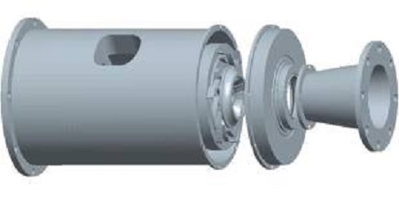
The Francis turbine with a new type of casing is developed, which can be applied to the city water supply system for recycling the energy from un-used pressure at the end stage of pipe line, as shown in Fig. 1.
Before commercialization of this turbine, feasibility analysis of inline casing is necessary. The applicability of guide vane and runner equipped in inline Francis turbine had been explored in another study(2, 3). Therefore, this study is focused on the shape of inline casing. The strategy is to apply different shapes of belt passage, vertical corner and stay vane to investigate the variation of performance and internal flow.
2. Inline Francis hydro turbine model
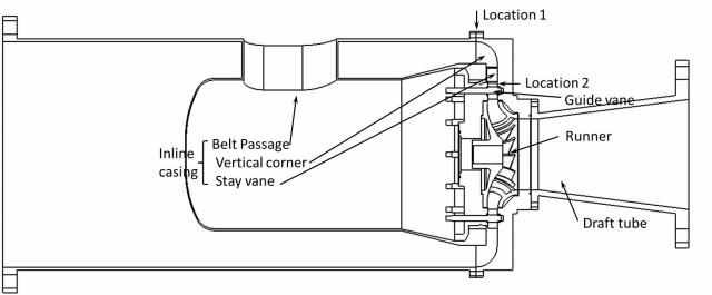
This inline Francis Turbine is designed with 4 main hydraulic components: inline casing, guide vanes, runner and draft tube as shown in Fig. 2. The rotational speed of the runner, effective head and flow rate at the design point are listed in Table 1.
Different shape of flow passage is designed for exploring the feasibility of this turbine, also with the attempt of improving the turbine’s performance.
As shown in Fig. 2, the location 1 is marked after belt passage for checking the velocity variation, and location 2 is marked at the stay vane tailing edge for checking the circumferential velocity in the following chapter.
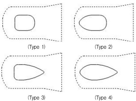
Figure 2 shows the cross sectional view of turbine flow passage. An avoidless vertical corner occupies the throat position of inline casing, located before the stay vane. A belt passage is designed in the column form body, used for the power transmission to the outside of the turbine casing from the runner axis. The belt passage shape is designed with different structures upstream and downstream the belt passage for checking influence of the flow by the belt passage shape, and named Types 1, 2, 3 and 4 as shown in Fig. 3.
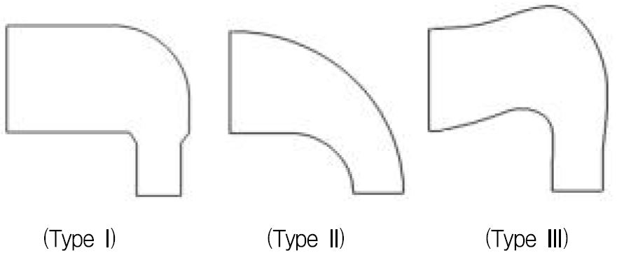
Three different types of vertical corner are designed as shown in Fig. 4. Type I is designed with a small filleted corner with a contract and linear downstream passage. Type II is designed with a uniform gradient curved transition, and Type III is designed with an outward corner for obtaining a longer adjusting passage before the flow accesses to the guide vane.
To offset the lack guidance function in circumferential direction of inline casing, the length of stay vane is extended to direct the flow towards the guide vane with an optimal incidence angle and also to carry the pressure loading. Figure 5 shows two types of stay vane and its location. The design method of the short stay vane (Type A) is referred to the stay vane which is used in the spiral casing turbine(2). The inflow angle of the long stay vane (Type B) is kept the same with short stay vane (Type A), only the leading edge of stay vane is extended to the vertical corner.
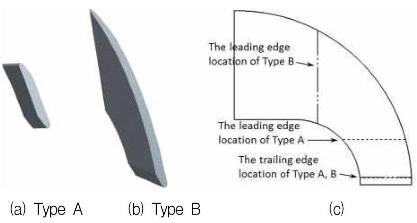
(a)short stay vane; (b)long stay vane; (c)sketch drawing of stay vane location with the vertical corner Type II
Table 2 shows the cases with different inline casing shapes, which are designed for investigating the influence of different belt passage type, vertical corner type and stay vane type, respectively. Among the Cases A, B, C ,D, different belt passage type is used, and fixing the type of vertical corner and stay vane with Type I and Type A. Among the Cases D, E, F, only the vertical corner type is variable, the other two types are fixed, as well as Cases G, H, I. Comparing Case D to Case G, Case E to Case H and Case F to Case I, the influence of different stay vane type can be obtained.
3. Numerical methods
Computational Fluid Dynamics (CFD) analysis is a very useful tool for predicting hydraulic machinery performance at various operating conditions(4-7). For the designer, prediction of operating characteristics is the most important task. This study employs a commercial CFD code of ANSYS CFX(8) to conduct CFD analysis.
The numerical methods and boundary condition are set as shown in Table 3. The general connection is set as the frozen rotor condition between the rotational area and the fixed area in the flow field for steady state calculation, and transient rotor stator is used in transient calculation.
The total pressure boundary condition is applied at the inlet of the calculation domain, and static pressure for the outlet.
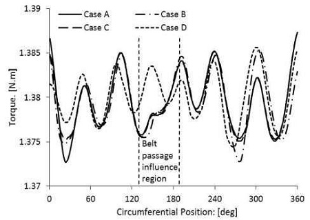
In this study, all the efficiency is obtained by using the results from steady state calculation, only the torque investigation in Fig. 10 uses the conjoint analysis of steady state and unsteady state calculations. The strategy of torque investigation is firstly to achieve a stable result by using steady state calculation, then to start the unsteady state calculation by applying the result from steady state calculation as the initial condition. This strategy is characterized by saving time and computational cost.
3.1 Validation analysis of numerical grids and turbulence model
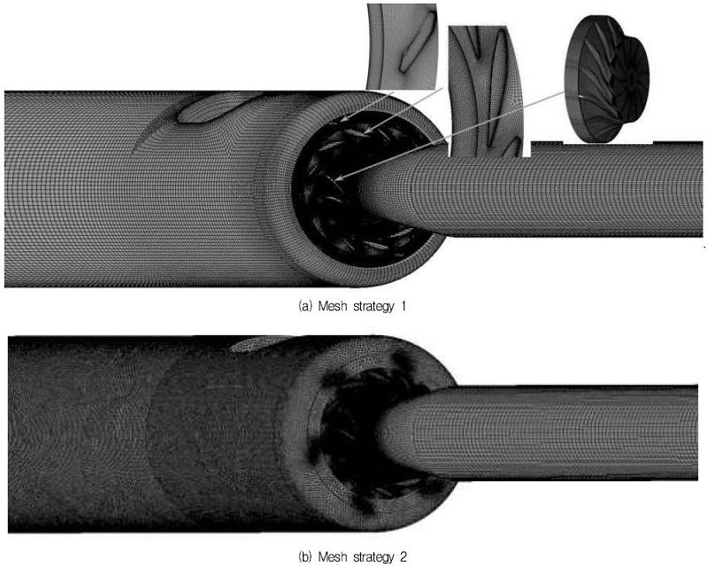
The mesh dependence analysis is carried out by applying different mesh types to the inline casing domain. Among the test analysis, the guide vane, runner and draft tube domain are fixed with high quality hexahedral grids. High quality hexahedral grid and high density tetrahedral grid are applied to the inline casing domain, relatively, as shown in Figs. 6(a) and 6(b). The efficiency change (Δη) between Case A and Case I is defined as the test object. As shown in Table 4, two mesh strategies show close value of Δη, relatively small difference proves the reliability of two mesh strategies. Finally, the mesh strategy 1 is selected for this study, the non-dimensional wall distance of Case A is shown in Table 5.
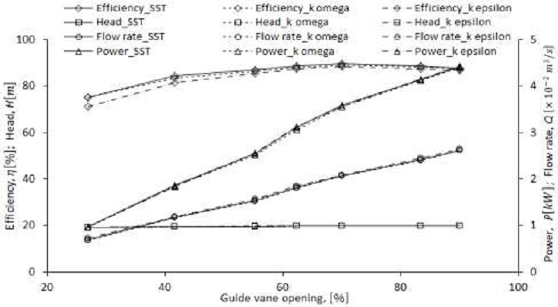
The turbulence model test also needs to be carried out to validate the results of this study. In this study, three turbulence models of SST, k-ω, k-ε were tested with same boundary conditions and numerical methods. Figure 7 presents the tested results of performance curves by the Case I, which show good correlation of the performance curves by each turbulence model. Finally, the shear stress transport (SST) turbulence model is utilized, which has been well known to estimate both separation and vortex occurring on the wall of a complicated blade shape.
4. Results and Discussion
4.1 Performance curves
When the water flows through the turbine, hydraulic losses may occur due to eddy formation in different components, change in flow direction and as well as due to loss in kinetic energy at the exit of the turbine. Considering only the hydraulic loss, the turbine efficiency is calculated by the following Eq. (1):
| (1) |
Where η is the efficiency of the turbine; T is the torque on the runner; ω is the angular velocity of runner rotation; ρ is the water density; g is the gravitational acceleration; Q is the flow rate; H is the effective head.
In order to investigate the turbine performance in the actual operating condition, the prediction is carried out by fixing the pressure at the turbine inlet and outlet (fixed head=20 m). The overall performance of the turbine with inline casing shape of Case I is presented in Fig. 7, with various guide vane opening. The efficiency curve by SST turbulence model shows that the turbine can be operated at a relatively high and stable value, the minium efficiency of 75.02% appears at guide vane opening of 27% and the maximum efficiency 89.51% appears at the guide vane opening of 70%.
4.2 Comparison of different belt passage shape
As the belt passage shape is conjectured to give a relatively large influence to the internal flow and performance of the turbine model, comparison of different belt passage shape is conducted.
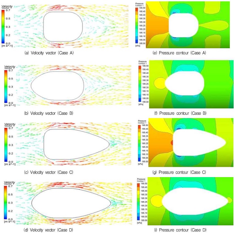
Among Cases (A~D), the Type I of vertical corner and the Type A of stay vane are applied. From Fig. 8 (Case B and Case D), it can be observed that the relatively elliptical shape in the leading edge gives a smooth guidance to the flow. Comparing the Cases A and B to Cases C and D, more uniform velocity in the passage trailing edge is obtained at Case C and D. The relatively sparse area of velocity distribution behind the passage is eliminated. In addition, Cases A and C show a relatively high pressure loading at the leading edge and low pressure area on the two sides. In Case D, the pressure contours show more gradual variation along to the flow direction. The high pressure loading in the leading edge disappears ascribing to relatively uniform flow.
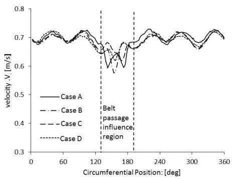
The stay vane and guide vane are designed with a angle to achieve the flow entering the runner with no shock. Therefore, the flow will be lead with a circumferential velocity around the stay vane and guide vane region, giving a explanation that the location of belt passage influence region in the stay vane, guide vane and runner is shifted a little to the clockwise direction, not absolutely symmetrical distribution at the position of 180°, as shown in Figs 9 and 10. In addition, the range of belt passage influence region shown in Figs. 9 and 10 is approximate.
Figure 9 presents the value of velocity, at the location 1 marked in Fig. 2, which is influenced by the different belt passage, giving the same indication that Case D shows relatively uniform velocity distribution and gives smaller influence to the flow than the other cases, the velocity at the belt passage influence region of this case shows relatively uniform distribution.
A further investigation of the influence by belt passage is carried out by the torque distribution on the runner single blade as shown in Fig. 10. The belt passage type of Cases A, B and C causes a relatively low torque in the belt passage influence region. And a small improvement of torque distribution is obtained by Case D, at the belt passage influence region.
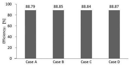
Efficiency comparison of all cases with different type of belt passage is carried out and summarized by the histogram as shown in Fig. 11. From the efficiency histogram, a estimation can be made on the influence of different belt passage shape. The efficiency of four cases shows almost similar value, and a relatively higher efficiency of 88.87%, is obtained by Case D, which has elliptical shape of the leading and trailing edges of belt passage.
4.3 Comparison of different vertical corner shapes and stay vane
The influence of different vertical corner and stay vane shapes is investigated by fixing the belt passage shape with Type 4.
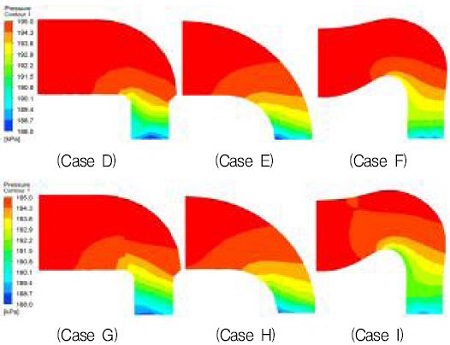
Figure 12 shows the pressure gradient along the flow passage in the vertical corner. The Cases E, F and H, I are designed with a uniform gradient curved transition which gives soft guidance to the flow, proving by the more uniform pressure decrease. The investigation of different stay vane type is carried out by comparing the pressure distribution of Cases D, E F with cases G, H, I. It shows that the long stay vane promotes the pressure gradient to gradually change when the fluid flows through the vertical corner.
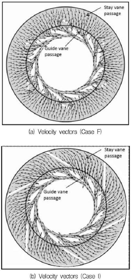
To deepen the investigation of the influence of the different stay vane type, the velocity vectors of Cases F and I at the front view of the stay vane and guide vane passage are shown in Fig. 13. The flow in the stay vane passage is almost in the radial direction in the Case F, and a relatively disordered flow condition around the stay vane and guide vane is observed. The velocity vectors of Case I show that the circumferential direction of the passage flow along the guidance of the stay vane passage. Flow enters the guide vane passage with a relative uniform direction, the disorderly flow pattern around stay vane and guide vane is removed.
Figure 14 shows the circumferential velocity at the location 2 marked in Fig. 2. Cases H and I show relatively higher circumferential velocity than that of Case G at the crest points as shown in Fig. 14(a).
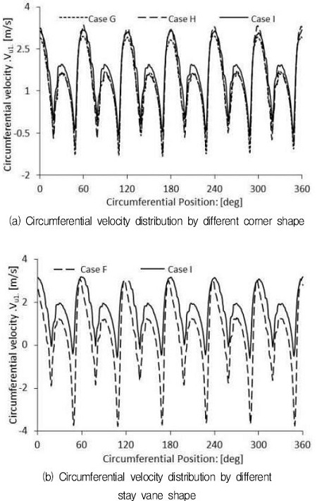
Circumferential velocity distribution by the different corner and stay vane shapes at the location 2
Agreeing with the indication from Fig. 13, the short stay vane presents low ability in changing flow from radial to circumferential directions, as Case F shows smaller circumferential velocity with large fluctuation in Fig. 14(b). And, comparing Case I with F, it shows that the circumferential velocity increases by the relatively long stay vane shape.
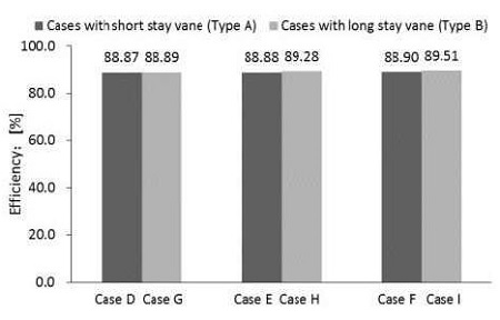
Figure 15 presents the efficiency by the different vertical corner and stay vane shapes. The efficiency of all cases show similar values, and the maximum efficiency of 89.51% is obtained at Case I. It implies that the turbine performance with inline casing is stable and relatively good regardless of the passage shape difference.
5. Conclusions
This study presents the feasibility analysis of a Francis turbine with inline casing. The inline casing replaces the spiral casing, characterizing the turbine with simple and compact-size property. In order to commercialize the inline hydro turbine, the effect of passage shape on the performance and internal flow of the turbine is examined. According to the shape of the belt passage, vertical corner and stay vane, the effect on the turbine performance is extremely small, even the change of stay vane shape does not give large difference. Nevertheless, the efficiency of the inline Francis hydro turbine shows relatively high value of 89.51%, regardless of the passage shape difference, which indicates the newly designed inline Francis hydro turbine can be applied effectively to city water supply system.
Acknowledgments
This work was supported by the New and Renewable Energy of the Korea Institute of Energy Technology Evaluation and Planning (KETEP) grant funded by the Korea government Ministry of Trade, Industry and Energy (No. 2013T100200079)
References
- Layton, E. T., (1992), “From Rule of Thumb to Scientific Engineering: James B. Francis and the Invention of the Francis Turbine”, NLA Monograph Series.
-
Wei, Q. S., and Choi, Y. D., (2013), “The Influence of Guide Vane Opening on the Internal Flow of a Francis Turbine”, Journal of Korean Society of Marine Engineering, 37(3), p274-281.
[https://doi.org/10.5916/jkosme.2013.37.3.274]

-
Wei, Q. S., Zhu, B. S., and Choi, Y. D., (2012), “Internal Flow Characteristics in the Draft Tube of a Francis Turbine”, Journal of Korean Society of Marine Engineering, 36(5), p618-626.
[https://doi.org/10.5916/jkosme.2012.36.5.618]

-
Jingchun, W., Katsunasa, S., Kiyohito, T., Kazuo, N., and Joushirou, S., (2007), “CFD-Based Design Optimization for Hydro Turbines”, Journal of Fluids Engineering, 129, p159-168.
[https://doi.org/10.1115/1.2409363]

- Alnaga, A., and Kueny, J. L., (2008), “Optimal Design of Hydraulic Turbine Distributor”, WSEAS TRANSACTIONS on FLUID MECHANICS, 3(2), p175-185.
- Shukla, M. K., and Jain, R., (2011), “CFD Analysis of 3-D Flow for Francis Turbine”, Int. Jour. Mechanical Engineering, 2, p93-100.
- Navthar, R. R., TejasPrasad, J., Saurabh, D., Nitish, D., and Anand, A., (2012), “CFD Analysis of Francis Turbine”, International Journal of Engineering Science and Technology, p3194-3199.
- ANSYS Inc, (2012), “ANSYS CFX Documentation”, Ver. 12, http://www.ansys.com.
