Development of a Submerged Propeller Turbine for Micro Hydro Power
Abstract
This paper aims to develop a submerged propeller turbine for micro hydropower plant which allows to sustain high values of efficiency in a broad range of hydrological conditions (H=2~6 m, Q=0.15~0.39 m3/s). The two aspects to be considered in this development are mechanical simplicity and high-efficiency operation. Unlike conventional turbines that have spiral casing and gear box, this is directing driving and no spiral casing. A 10 kW class turbine which has the most high potential of the power generation has been developed. The most important element in the design of turbine is the runner blade. The initial blade is designed using inverse design method and then the runner geometry is modified by classical hydraulic method. The design process is carried out in two steps. First, the blade shape is fix and then other components of submerged propeller turbine are designed. Computational fluid dynamics analyses based on the Navier-Stokes equations have been used to obtain overall performance data for the blade and the full turbine, respectively. The results generated by performance parameters(head, guide vane opening angle and rotational speed) variations are theoretically analysed. The evaluation criteria for the blade and the turbine performances are the pressure distribution and flow's behavior on the runner blades and turbine. The results of simulation reveals an efficiency of 91.5% and power generation of 10.5kW at the best efficiency point at the head of 4m and a discharge of 0.3 m³/s.
Keywords:
Turbine Blade, Submerged Propeller Turbine, Euler Equation, Inverse Design Method, Hydraulic Design Method, Computational Fluid Dynamics, Cavitation키워드:
터빈 블레이드, 수중 프로펠러 터빈, 오일러 방정식, 역설계방법, 수력학적 설계 방법, 전산유체역학, 캐비테이션1. Introduction
Rapid depletion of conventional energy resources, fossil fuel burning and global warming, as well as safety issues of nuclear power have raised a great concerns on clean renewable energy resources which is commonly referred to both traditional biomass and modern technologies based on solar, wind, biogas, geothermal, and small hydropower. Among them, small hydropower is the most prospective form of renewable energy. Wherever resources exists, it can provide cheap, clean and reliable electricity. A well designed, small hydropower system can blend with its surroundings and have minimal negative environmental impacts.(1)
Moreover small or micro hydropower generation has a huge potential, as yet untapped potential, which would allow it to make a significant contribution to future energy needs. The development activities rely on largely proven and developed technology, which still have a considerable scope for development and optimization of this technology. Low head small or micro hydro power system are one of the best options for the excavation of the potential energy resources.
A propeller turbine has fixed blade and its cost are appreciably lower than that of Kaplan turbine. One of best ways to overcome the efficiency drop of constant speed-propeller turbine’s partial and over load operations is to use the variable-speed operation technique. Another alternative option is adjusting its structure.(2,3)
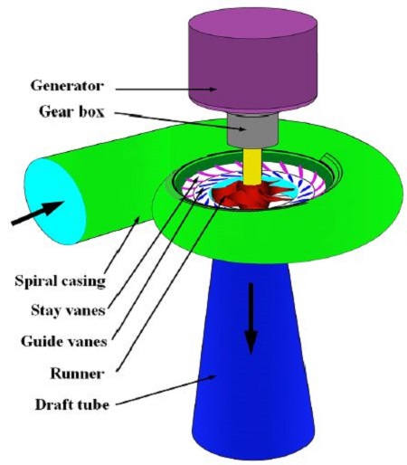
Typical propeller turbines are equipped with a spiral casing, stationary vanes, guide vanes, runner , gear box, generator, and a draft tube as shown in Fig. 1.
The runner is connected mostly to the an asynchronous generator by means of a mechanical transmission, that is, gear box. Its position is most commonly mounted in a spiral casing which is a spiral passage for directing the water from the penstock around a water turbine and into the runner blades.
Micro and pico hydro turbines are normally operated under very low heads and discharges conditions. For very low heads(below 4 m) the spiral casing is not recommended because it creates a high velocity at the inlet to the runner, which causes a very low pressure area on the blade. Because of larger capacities which is occupied by considerable space around turbine and efficiency drop and shaft sealing handicap of very low head condition. Spiral casings also require more sophisticated fabrication than other components. Another obstacle in typical small hydro turbine is gear box. Because the typical gearbox contained gears running in oil, it may be cause of environmental contamination by oil spill. Moreover there is significant friction loss in the gearbox. Therefore the necessity of developing a substitutional equipment of a suitably compact form is becoming a key issue for development of micro and pico hydro turbine circles.(1)
To overcome the technical and economic drawbacks of small hydro turbine using a limited water resources, there is needed to design a simple machine for keeping high efficiency.
The main concept of the turbine development for very low heads and discharges is high efficiency, simple maintenance and high economic viability. In order to meet the development concept, the desirable layout of a new propeller turbines is to eliminate spiral casings with fixed vanes and gearbox. Submerged turbines are mainly used for the water current turbines or hydro-kinetic turbines to harness ocean and river current energy. There is no report for submerged hydro turbine in small hydro turbine at the moment.
The present study focuses on development of a high-efficiency runner blade and direct driving submerged propeller turbine.
2. Preliminary design
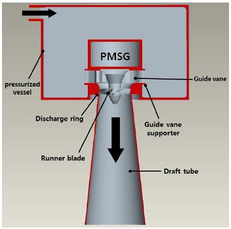
The turbine is designed as a submerged vertical axis or pressurized vessel with movable 20 guide vanes which are attached the guide vane supporter, runner blades which are directly attached to the end of permanent magnet synchronous generator (PMSG) shaft without requiring a speed increasing drive system, and straight conical draft tube which was chosen to ensure maximum recovery with minimum loss as presented in Fig. 2. Because the generated is submerged, there is no an auxiliary device for the generator cooling. This particular layout was chosen for the low head and flow rate (without likelihood of cavitation), direct driving of generator, compact and simple mechanism. This specific feature enables the system simplicity, less maintenance and economic viability. The specification based on the turbine design is given in Table 1.
When comparing different turbine designs, specific speed is a useful parameter for grouping families of turbine, that is turbines of similar shape but different size and speed. The initial step of the turbine design is to decide the specific speed (ns) value. There are many different forms of the specific speed. For this study we use the following equation.
| (1) |
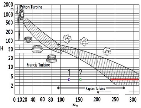
This number gives an indication of the geometry of the turbine and it is the starting point for detailed design. The choice of the blade rotational speed depend on the generator and the type of drive used. We adopt two cases(600 rpm,750 rpm) of rotational speed in this study. Comparing this specification with statistical data from literature and from our own experience it can be clearly be seen, that the specification of this low speed leads to a non-standard design, see point 1 in Fig. 3.(4)
From point 1 in Fig. 3 (in case of 650 rpm) it can clearly be seen that the specific speed (ns) is much lower compared to standard designs (red line). The design speed of a turbine is largely determined by the head under which its operation. A newly developed optimal runner blade should be compatible with low specific speed.
These values agree with statistical values in the literature.(4) The specific speed of the turbine is 156 in the nominal point.
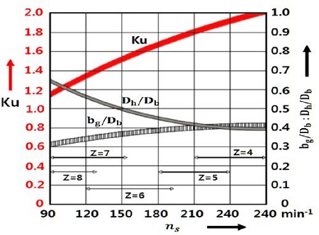
From Fig. 4, the value of Ku (1.55) can be obtained, this results in a turbine diameter of
| (2)(4) |
where Ku is non-dimensional blade velocity ().
The main data of the turbine blade are summarized in Table 2.
Then hub geometry is determined by the low specific condition. The large hub is necessary because of the low speed the bending of the runner blade is extreme at the hub.
3. Geometric design of propeller turbine
3.1 Runner blade design
The energy transfer taking place in runner passage is more complex than that in the other parts of the turbine. Hence, first work is focused on the runner only.
There are two approaches for hydro turbine design, those are, direct design method and inverse design method(5). In the direct method, the blade shape for earlier design is specified and then modified iteratively by trial and error using computational fluid dynamics to check whether the required flow field like pressure distribution is obtained. Designers require skillful experience on the hydro turbine design. On the other hand, the blade geometry in the inverse method is computed iteratively for a specified blade loading distribution, especially for designs without any reference.
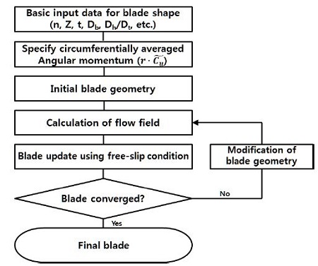
For initial blade design the commercial 3D inverse design code TURBOdsign-1 was used as the design methodology in this study(5). As shown in Fig. 5, the inverse design procedure, the solver code and the blade design algorithm are coupled to form an auto-matched design cycle. The geometry of the blade is determined by the change in angular momentum ∂(rCu)/∂m along the meridional streamline. the rCu distribution is not specified directly but through the specification of ∂(rCu)/∂m, which directly relates to the pressure loading on the blade.
Within the assumption of an incompressible potential flow, the static pressure difference across the blade is related to the tangentially-averaged swirl velocity, that is,
| (3) |
Here m=0 means at the leading edge and m=1 means at the trailing edge.
Equation (3) shows the relation of the surface pressure to the loading distribution , therefore by specifying a smooth blade loading distribution, it is also possible to ensure smooth surface pressure variations. All these criteria are found to be more easily satisfied by specifying the loading distribution rather than the distribution.(5,6)
The following steps will be taken to create suitable rCu and loading specification for a given design.
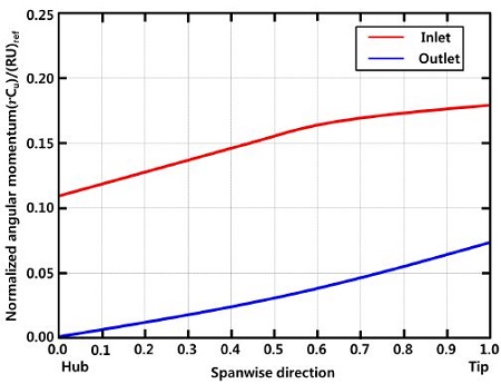
step 1 : Impose rCu span-wise distribution at theinlet section (Fig. 6)
step 2 : Impose rCu span-wise distribution at theoutlet section (Fig. 6)
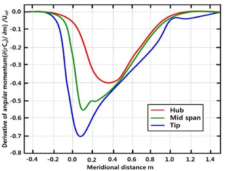
step 3 : Impose distribution on severalstream -wise inside the blade (Fig. 7)
Angular momentum is normalized by the turbine speed and reference angular momentum (RU)ref, where R=0.175 m is the runner radius and U is the peripheral speed at this radius. Fig. 6, shows angular momentum at the inlet and outlet have gradually increase as the span-wise direction. The meridional angular momentum derivative along the streamline at three span-wise sections is shown in Fig. 7. The depreciation of the swirl starts before it reaches the leading edge of the blades and it gets the lowest values.
Key point of the blade design by inverse design method is to find the optimal loading distributions properly. However, the approach is mainly depend on empirical perspective. Although the commercial softwares are getting more accurate, fast and userfriendly, they do not provide the initial condition able to automatically optimize the performance of a geometry. Unskilled or unexperienced designers should modify or optimize the reference blade in order to obtain a better design plan with good performance . Modification method on reference blade is better simple approach than multi-optimization method.(7) In this study the reference runner blade was modified in order to reach the highest possible top efficiency level.
From Equation (1), it is obvious that the specific speed is proportional to discharge, for constant n and H. The lower of specific speed means decreasing the discharge regulating by guide vane. An increase of discharge Q means to adjust the guide vanes to a larger angle.
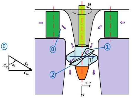
The submerged propeller turbine uses an adjustable guide vanes (20~60 degrees) that directs water onto the runners. The propeller blades are fixed as shown in Fig. 8. For the description of velocity triangles, the outlet of the guide vane opening angle α0 marked (0), and the inlet and outlet of the runner marked (1) and (2) respectively. The water exits through a conical draft tube.
Propeller turbine intends to have poor efficiency characteristics for the low specific speed condition.
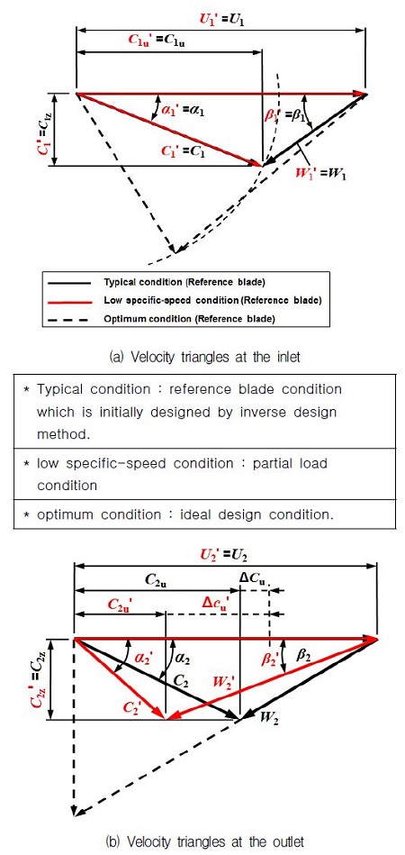
Under the low specific speed condition, corresponding to partial load, a modified runner blade based on the initial runner blade by inverse design method is obtained by hydraulic design method. There are two major parameters to influence the efficiency of low specific speed turbine. The one is the runner stacking condition. Optimal stacking condition is already considered in preliminary study. The other is blade shape angles (β1,β2) at the inlet and outlet respectively. The velocity triangles of inlet and outlet of the reference runner on the design condition and under the low specific speed condition at a constant head and rotational speed are shown in Fig. 9.
As shown in Fig. 9, the value of absolute velocity (C1 and ) at the inlet is constant determined to hydraulic head H, its direction changed with the opening of guide vanes. As the inflow is decreased, the entrance angle is decreased from α1 to . From the Euler equation of turbine, the hydraulic efficiency of turbine (neglecting losses) on design condition is defined as follows,
| (4) |
Since the blade velocity (U1,U2) is constant determined to power grid frequency and rotational component of absolute velocity (C2u) at the outlet in design condition is zero, that is,
| (5) |
Thus the turbine efficiency (η) of the design condition is
| (6) |
The efficiency of turbine is only dependent on rotational component of absolute velocity at the inlet.
As the inflow is decreased, the entrance angle at the inlet is decreased from α1 to and absolute velocity rotational component is changed from C1u to C1u′ at the inlet. Since the angle of the propeller turbine blade is fixed, so the blade angle at the outlet β2′ is not changed but rotational component of absolute velocity is changed C2u(=0)→C2u′. Thus, the efficiency (η′) of turbine on low specific speed condition is changed as follows :
| (7) |
It can be seen from Fig. 9, that the C2u′ is rather large, so the difference (C1u-C2u) is larger than that of (C1u′-C2u′).
Since C2u = 0 from velocity triangle, it is clear that C1u ≫ (C1u′- C2u′. In comparison with the equation (6) and (7), the efficiency of the low specific speed condition is lower than that of design condition, η′ ≪ η.
In addition to the efficiency deficit, it will cause periodic pressure pulsation by vortex and poor recovery of kinetic energy in draft tube due to the whirl component of absolute velocity at the outlet.
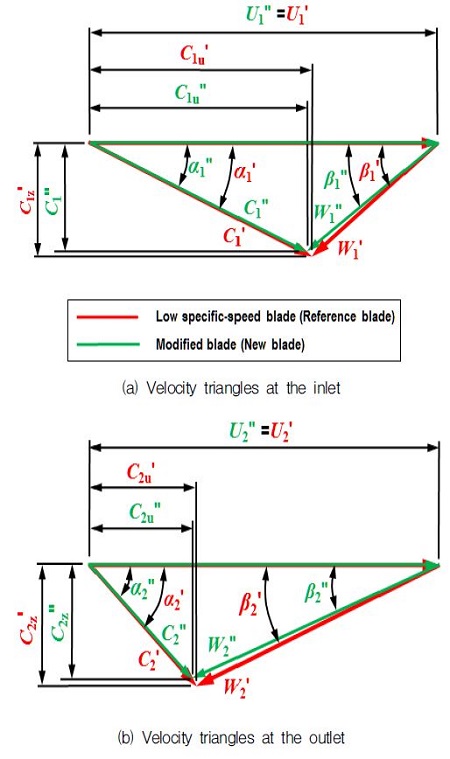
Using velocity triangles in Fig. 10, the net rotational component of absolute velocity is as follows,
| (8) |
Fig. 10, shows the velocity triangles at the inlet and outlet of the airfoil on the cylindrical surface under the design condition (black line) and low specific speed condition (green line) and also represents the velocity vector at the inlet and outlet of optimized runner (red line) to increase the efficiency.
To get over these kind of draws, as shown in Fig. 11, the ideal condition of blade shape is extinguish the impacting loss of the incoming flow as β1″→ β1′at the inlet and simultaneously the outlet flow angle α2 = 90o and the rotational component of relative velocity at the outlet C2u′= 0, where C2u′ is in opposite direction with the blade velocity U2, and the swirl counterrotates with respect to the runner, i.e., C2u′=0. But it does not really happen. The geometrical modifications based on velocity triangles were implemented on reference runner blade.
Because the rotational components of relative velocity at the inlet and outlet is not changed, C1u″= C1u′. The efficiency (η″) of modified blade from Equation (9) is expressed as follows :
| (9) |
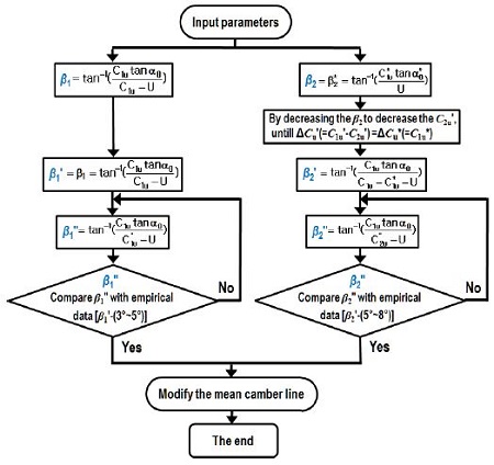
It can be found that the efficiency (η″) gains from decreasing the value . This is similar to Kaplan turbines in which the blade is rotated in pitch direction, from a flat profile for very low flows to a heavily- pitched profile for high flows, to maintain a high efficiency at part load, with the speed of runner remaining constant. The modified blade angles are to bring the condition, β2′→ β2″, and the difference of rotational component of relative velocity of target runner between inlet and outlet approach to the value of -the corresponding relative velocity of design conditions, (C1u′- C2u″)→C1u,or efficiency close to rated efficiency (η) with iteration.
In order to modify the shape of reference blade, the modification procedure is shown in Fig. 11.
3.2 Pressurized vessel, guide vane and draft tube design
There is significant difference in turbine appearance with spiral casing. A pressurized vessel is a closed container designed to hold water at constant pressure and it is designed to provide stability and durability as well as to keep a certain pressure level and water balance of stored water. Pressure vessel is made of concrete excepting steel manhole cover. Volume of the pressurized vessel is to meet the requires flow rate of turbine during turbine operation from reference as follows :
| (10) |
Basic purpose of the guide vane is to convert a part of pressure energy of the fluid at its entrance to the kinetic energy and then direct to the fluid on the runner blade at the right angle. The guide vane impart to a tangential velocity and hence an angular momentum to the water before its entry to the runner. In this study guide vane shape is designed using reference airfoil, NACA 23012 which is known for having a relatively high maximum coefficient of lift.(7) The height of guide vane is obtained from the following empirical expression(4) :
| (11) |
The guide vanes are pivoted and arranged between two parallel guide vane supporter. The guide vanes can be turned by hydraulic actuating units to regulate the flow while the load changes. The number of guide vanes has to be different from the number of runners as follow(4) :
| (12) |
In this study the number of guide vanes based on the equation (12) is 20.
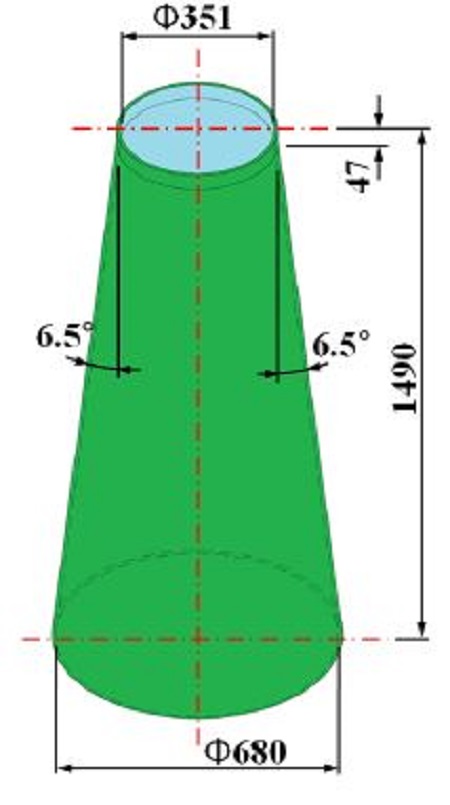
The main functions of draft tube is to allow the installation of turbine above the tail race level without loss of head and to convert major part kinetic energy coming out of runner into pressure energy. In this study to curtail the efficiency drop of turbine for low specific speed, the shape of tube adopted vertical divergent conical draft tube as shown in Fig. 12.
The cone angle is restricted to 8 degrees to avoid the losses due to separation.(7)
4. Numerical analysis
4.1 Numerical analysis on blade
As mentioned above, the turbine runner is equipped with 6 blades.
For the runner optimization a periodic flow is assumed, which means that each runner channel behaves equivalent. Boundary condition represents the known values within the end of the spatial domain for any temporal variations. The inlet and outlet boundary conditions are as follows:
The inlet boundary conditions used in this simulation is mass flow rate. At the inlet uniform transport velocity distribution (calculated from the assumed discharge) is applied. The fully developed flow profile is more physically realistic than a uniform profile. But we focus on the verification the static pressure behaviors of designed blade through the simple simulation. The influence of boundary condition on the simulation results goes beyond the scope. The swirling component is depending on the radius. It is calculated from Euler turbine equation.
| (13) |
At the outlet of the calculating domain a free out-flow is assumed (zero pressure at runner the outlet). At the both sides (blade to blade) periodic boundary conditions are applied. At hub and shroud wall conditions are put on. The gap between runner and shroud is neglected in the simulation.
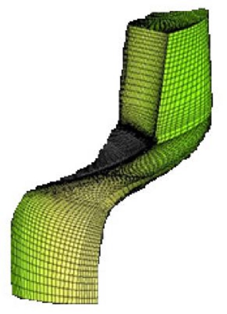
To discrete the geometry properly, an automatic mesh generator is applied. The computational grid for the runner is shown in Fig. 13. It consists of approximately 1,000,000 nodes for one runner channel.
Simulations are performed for the standard k-ε turbulence model.(8) Wall functions are introduced in the wall region, where eddy viscosity anisotropy is increased.
The calculation for the new runner is carried out using FENFLOSS (Finite Element based Numerical Flow Simulation System) developed by IHS (Institute of Fluid Mechanics and Hydraulic Machinery) of Stuttgart University.(3) The specialized software for hydro turbine, FENFLOSS uses a distributed memory approach based on MPI (Message Passing Interface). The main advantage of this approach besides a very good speed-up ratio, is the independence of solution from the number of partitions. This allows the usage of massively parallel architectures such as PC-cluster.
4.2 Numerical analysis on a submerged propeller turbine
An open flume or pressurized vessel turbine was designed according to the specification. The blade was designed for fixed guide vanes. This study also considered the influence of the net head variations (2~6 m), and guide vane opening (20~60 degrees).
The computational preprocess including the model and non-structure mesh generation is carried out using the commercial software STAR CCM+.(9) This CFD code solves the 3-D steady and incompressible Reynolds-averaged Navier-Stokes equation(RANS).(8)
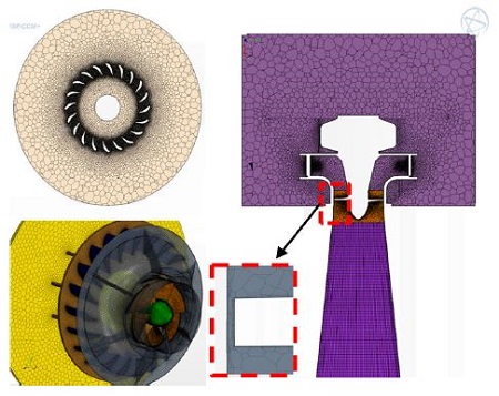
The modelling and grid generation of newly developed propeller turbine system are shown in Fig. 14. About the inlet boundary condition at the upper part of the pressure tank, it is assumed the uniform velocity distribution. As for the outlet boundary at the draft tube exit, the average gauge pressure is set to fix. In addition no slip condition is applied to the wall(surface). In order to accurately simulate the flow field, further mesh size to assess the impact of the gap size between turbine tip and discharge ring on the turbine performance are refined in guide vane and turbine passage. After the test of grid dependency on simulation results, final grid system is adopted as shown in Fig. 14.
The complete mesh consists of over 3.8 million polyhedral elements. Prism layer cells are used for capturing flow characteristics of boundary layer near wall. To model the turbulent flow, the k-ω shear stress transport (SST) turbulence model was used.(8)
5. Results and Discussions
5.1 Blade modification effects
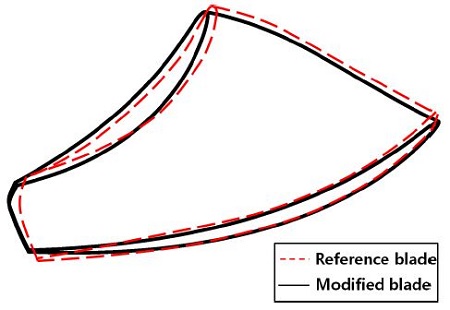
As depicted in velocity triangle diagram, runner blade performance depends essentially on the extent to which the blade is capable of extinguishing the rotational component (Cu) of water. Geometrical modifications based on the hydrological method carried out on the reference runner. The profile of modified and reference blades is compared in Fig. 15, and the typical values of blade angle at the different locations are also presented in Table 3.
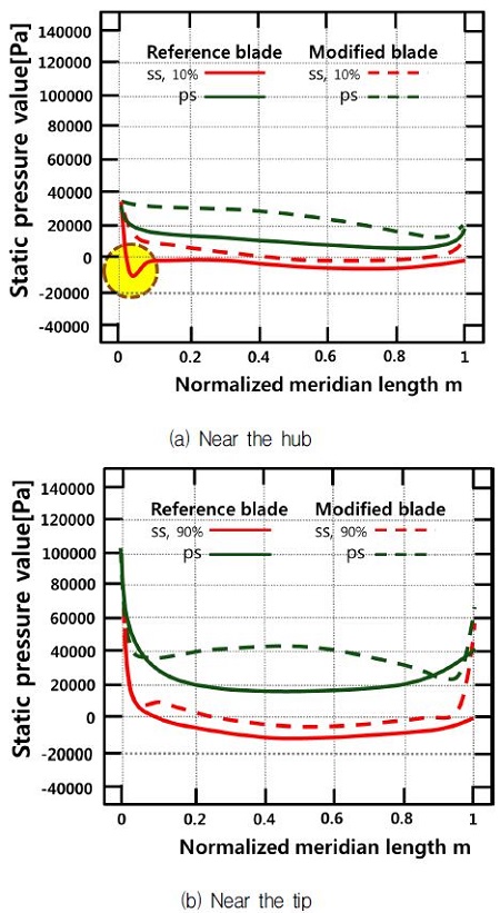
Blade parameters like inlet and outlet angles, specific speed influence cavitation which does greatly affects the turbine performances. Cavitation in the turbine runner blade occurs when the static pressure of the passage water falls below vapor pressure. The static pressure curve on the blade is a basic indicator of blade design.
As shown in Fig. 16, (a) the static pressure of suction side for reference blade shows a rapid pressure drop below zero near the leading edge.
This is attributed to the unnatural strike on blade leading edge near the hub of coming flow. On the contrary, the pressure distribution of suction side for modified blade indicates smooth curve due to the optimal strike on blade. From the pressure curves, it is seen that the pressure loading on hub is considerably improved by the modification of the reference blade.
The pressure loading characteristics on blade is seen clearly in Fig. 16, (b) near the tip. Especially pressure difference of two blades in middle area between leading edge and trailing edge is clear. It is evident from the result shown that pressure difference between the pressure side and suction side of modified blade is much higher than those of the reference blade. Results confirm that the pressure difference of pressure and suction side of runner blade attribute to the extraction of water energy by the turbine runner.
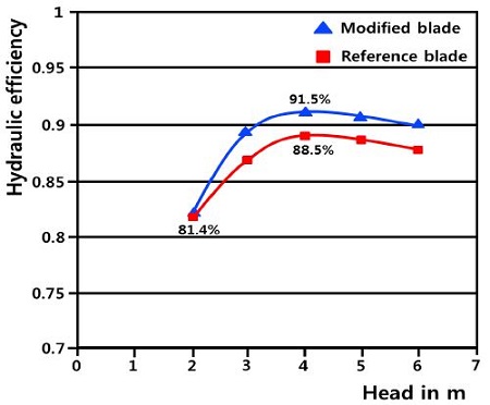
Fig. 17, shows the efficiency comparison of two blades with respect to head variation. It is seen that the runner efficiency at the head H=4 m (design head) is the highest. From this figure it can be found that the modified blade yields 3.0% increase in peak efficiency.
5.2 Performance of a submerged micro propeller turbine
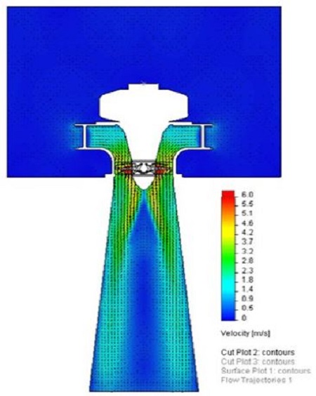
The numerical analysis has been used to verify the performance of the submerged micro propeller turbine. The velocity contour of the flow field obtained with full simulation domain from the pressure tank to the draft tube is shown in Fig. 18.
It can be found that the flow evolute toward the guide vane in the pressurized vessel. The flow through guide vanes which give the flow a spin around the rotational center before it enter the runner is directed on to the runner and changes its direction from radial to axial. It is found that the flow patterns through guide vanes are similar to those of the conventional turbine with a spiral casing but the intensity of tangential velocity is much weak.
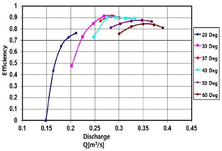
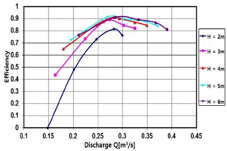
Fig. 19, represent the turbine efficiency characteristics with respect to the guide vane opening. The efficiency reach maximum in case of guide vane opening 37∘ . It can be seen that the efficiency curve at the partial load (α=20∘ ) is lower than that of the overload condition (α≥50∘ ). The turbine efficiency tendency with variation of heads are shown in Fig. 20. This indicates that the efficiency of turbine increases with increasing of discharge until reach the maximum point and then decreases gradually. This turbine shows good performance except the lowest head H=2 m which results the attribution of the unmatching the blade angle to the incoming flow.
6. Conclusion
A high-efficiency and simple(without spiral casing and gear box) submerged micro propeller turbine for very low specific speed condition is newly developed. The performance of the modified runner and newly developed turbine with respect to guide vane opening and head variations is investigated by the numerical analysis. From the simulation results, the following conclusions are drawn.
- 1) This type of turbine for very low head and small discharge can be more efficient, viable and economic than the corresponding typical turbine
- 2) The new modified runner blade induces an important minimum static pressure increase near hub of suction side and the modification method is also useful tool to increase the blade performance.
- 3) The turbine efficiency improvements with wide range of head and guide vane opening has been obtained and gained 3.0 % efficiency gain at the design head and discharge.
By means of the manufacturing of all components of the newly developed turbine, its performance and feasibility will be validated by prototype and site testings.
Nomenclature
| bg : | guide vane height (mm) |
| Db : | turbine blade diameter (mm) |
| Dh : | hub diameter (mm) |
| H : | head |
| Q : | discharge (m3/s) |
| ns : | specific speed |
| n : | rotational speed of runner blade (rpm) |
| w : | angular velocity of blade() |
| p : | pressure (Pa) |
| U : | circumferential velocity of turbine (m/s) |
| C : | absolute velocity (m/s) |
| W : | relative velocity (m/s) |
| Cmbl : | meridional velocity across the blade (m/s) |
| Z : | number of turbine blade |
| Ku : | non-dimensional blade velocity |
| k : | turbulent kinetic energy |
| ε : | turbulent dissipation |
| s : | tip clearance between blade tip and discharge ring (mm) |
| m : | meridional direction |
Subscript and superscript
| u, r : | circumferential direction(or component) |
| z : | axis direction |
| 1 : | inlet of blade |
| 2 : | outlet of blade |
| ' : | low specific speed condition |
| " : | optimal condition |
Acknowledgments
This work was supported by the Korea Institute of Energy Technology Evaluation and Planning(KETEP) grant funded by the Ministry of Trade , Industry & Energy.
References
- Omar, M-B., (2007), “Introduction to Small Hydropower Generation”, ARISER, 3, p26-59.
- Bard, J., (2000), European Status Report on Variable Speed in Small Hydropower, Brussel, DG Tren.
- Lippold, F., Gode, E., and Ruprecht, A., (2003), “On the Design of a Variable-Speed Turbine with Fixed Blades and Fixed Guide Vanes”, Proceeding of the International Conference on CSHS03.
- Bohl, W., (2005), Strömungsmachinen 2, Berchnung und Kakulation, Vogel Fachbuch.
- Advanced Design Technology (ADT), (2013), Turbo design suite.
- Höfler, E., Gale, J., and Bergant, A., (2011), “Hydraulic design and analysis of the saxo-type vertical axial turbine”, Transactions of the Canadian Society for Mechanical Engineering, 35, p119-143.
- Nechleba, M., (1957), Hydraulic Turbines Their Design and Equipment, ARITA.
- Ismail, B. C., (1999), Introduction Turbulence Modelling, Lectures Notes.
- Introduction to STAR CCM+, (2013), CD-adapco.
