Design and Experimental Analysis on 3kW class Pump Turbine Model for Renewable ESS
Abstract
Pump storage systems are an emerging technology in the field of hydropower. Pump turbines are considerably useful for the run-off-type hydropower. Pump turbines can be used to generate power and regulate water from the lower reservoir to the upper reservoir using a single unit. Pump turbines allow to maintain stable and renewable power generation. Unfortunately, there are no appropriate pump turbine designs because it is considerably difficult to maintain the performance of the pump turbine in both turbine and pump modes. In this study, the design and experimental investigation of the pump turbine have been discussed. A 3-kW-class pump turbine model was designed using a discharge gradient to head the gradient method, and the performance of the pump turbine was experimentally investigated. In addition, the cavitation test was performed for the 3-kW-class pump turbine model.
Keywords:
Pump Turbine, Design, Experimental Analysis, Performance, Cavitation, Renewable Energy키워드:
펌프 터빈, 설계, 실험 분석, 성능, 캐비테이선, 재생너지 저장장치1. Introduction
Electricity plays an important role in human life. In the past, the major source of energy was fossil fuel. Due to the excessive consumption of fossil fuel, the world is facing the environmental hazard. Nowadays, the source of energy is shifting from non-renewable to the renewable source. Renewable sources were able to contribute 26.5% of the total production of electricity(1). The demand of renewable energy sources is increasing rapidly. The energy production from renewable sources like wind, solar and tidal current is increasing drastically. The output power from the renewable energy is highly dependent on weather conditions. Therefore, renewable sources like solar, wind and tidal current cannot generate stable and continuous power supply. This makes impossible to collaborate the renewable energy with power grids for the sustainable future.
The electricity generated from renewable sources like wind, solar and tidal current is volatile and fluctuating. Energy storage system (ESS) plays an important role in controlling the frequency, mitigating voltage fluctuation and improving power quality. ESS is used to mitigate the problem like load levelling, peak shaving, frequency control, and reserve generation. Therefore, ESS can be used to stored the excess energy when renewable sources are available and reuse the stored energy when renewable sources are unavailable.
There are many ESS available in the market. ESS is mainly found in the mechanical, electrochemical and electromagnetic form. The selection of the ESS depends on its storage capacity and life span. The electrochemical and electromagnetic types of ESS are not able to store energy on a large scale. The disadvantages of using electrochemical and electromagnetic ESS are expensive, environmentally hazardous, inflexible in sizing and limited life cycle. Therefore, the mechanical energy storage systems were preferred over electrochemical and electromagnetic for large scale energy storage. The mechanical energy storage system consists of flywheel, compressed air, pump turbine. Among mechanical ESS, pump turbine has a minimum capital cost per unit of energy stored(2). Therefore, the pump turbine is an attractive choice for the future of energy storage system. Pump turbine is the solution for the fluctuation in power production from renewable sources and their inability to supply stable power in peak hours(3).
Pump turbine is the most widely used large-scale energy storage technology. The global pump hydro energy storage capacity reaches to 153 GW in 2017(4). It stores the electrical energy by storing the water from the lower reservoir to the upper reservoir in the off-peak period. The water stored in the upper reservoir is used to generate power in high demand conditions. The pump turbine is used to store 99% of the global large-scale electrical energy(5). Generally, the efficiency of pump hydro energy system ranges from 65-85%.(6,7). The power generation from the pump hydro system is the same as the hydroelectric plant. Therefore, the output of the pump hydro system is stable, flexible, and readily supply within a short period.
First pump turbine system was built in Italy and Switzerland in 1890(8). Knapp(9) performed the experiment on the centrifugal pumps to determine the complete characteristics in different operating conditions. Generally, the centrifugal pump was modified to operate in the turbine mode. There is no fixed process for the design of the pump turbine. Many kinds of research have been carried out to determine the performance, flow behavior and dynamic response of the pump turbine. Jain and Patel(10) have conducted a review on the pump turbine operating in turbine mode. Hasmatuchi(11) explained about the pump turbine operation in off-design condition. Guggeberger et al.(12) have used Particle Image Velocimetry to visualize flow pattern of a pump turbine in different operating conditions. Li et al.(13) have investigated the effect of blade number in the pressure fluctuation of the pump turbine in turbine mode. The selection of the runner blade should be made by considering hydraulic performance and stability of the pump turbine. Kirschner et al.(14) have conducted the experiment to determine the pressure fluctuation in the draft tube wall of the pump turbine. Kirschner concluded that at partial load and overload condition peak pressure fluctuation occurred at low and high frequencies(14).
In this study, 3kW class pump turbine system was designed for the small scale energy storage system. The performance prediction of 3kW class pump turbine is conducted by experimental analysis. The operation of the 3kW pump turbine required the low head of 15m. Therefore, pump turbine can use the energy from a renewable source to operate in pump mode and generate electricity at the on-peak period by turbine mode.
2. Hydraulic Design
2.1 Impeller Design
There are various theories available for the pump turbine design(15-17). Among them, a gradient of discharge variation to head variation by Kubota(18) was used for the design of 3 kW class pump turbine. Singh et al.(19,20) have suggested this method for the design of a pump turbine. The specification of the pump turbine model is shown in Table 1.
The specific speed of the turbine and pump are defined as follows:
| (1) |
| (2) |
where, nst and nsp are the specific speed of the turbine and pump respectively. Ht and Hp are the net head of turbine and pump mode respectively. Q, P and N are the flow rate, power, and rotational speed of pump turbine respectively.
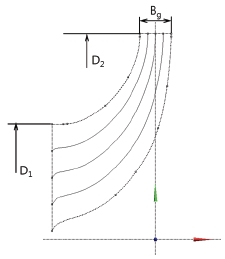
The meridional shape of the pump turbine impeller is shown in Fig. 1. The dimensions of the meridional shape are determined as follows:
| (3) |
| (4) |
| (5) |
| (6) |
where, u2 is the peripheral velocity at impeller exit, gQ/H is the head variation, D2 is the impeller exit diameter, cm1p is the meridional velocity at inlet, Bg is the impeller width, D1 is the impeller inlet diameter.
The pump turbine model has 5 impeller blades, 14 guide vanes, and 14 stay vanes. The inlet and outlet diameters for the impeller have been defined with respect to pump mode. The inlet and outlet diameters are 112 mm and 198 mm respectively. The impeller width is 15.2 mm.
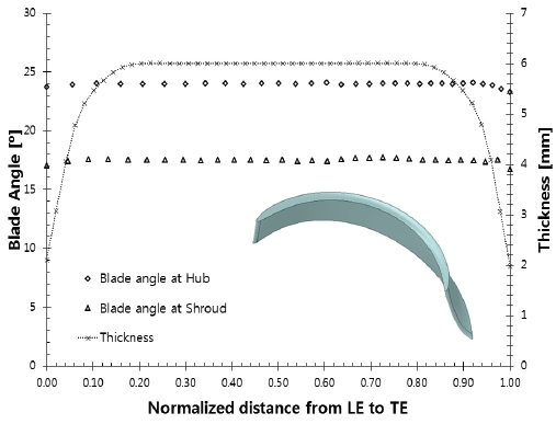
Fig. 2 shows the angle and thickness distribution of pump turbine impeller. The angle and thickness distribution from the leading edge to trailing edge of the pump turbine impeller is constant. The blade angles at the hub and shroud are 27.5˚ and 17.5˚ respectively. The blade angle of the pump turbine impeller is decreasing linearly from 27.5˚ to 17.5˚ from hub to shroud in the spanwise direction. The thickness of the impeller blade is 6 mm from leading edge to trailing edge.
2.2 Casing and Vane Passage Design
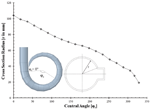
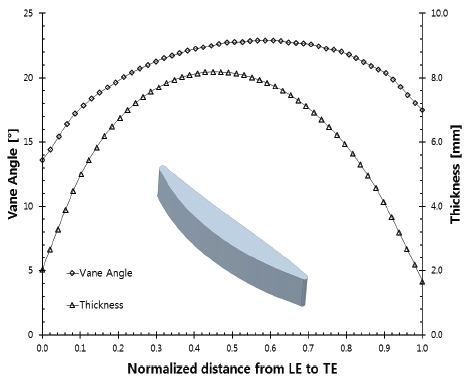
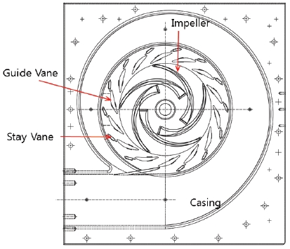
Fig. 3 and Fig. 4 indicate the design of the casing and stay vane for the pump turbine respectively. The design of the casing and stay vane play the significant role in maintaining proper flow in both mode. However, there is no requirement of stay vane for the operation of pump mode. But, it is necessary for maintaining the proper flow in the turbine mode. Therefore, the stay vane should be designed by considering the performance of both modes.
Free vortex type of casing is used for the uniform pressure distribution at outlet of stay vane. The cross section radius of the spiral casing is decreasing linearly from φc = 0˚ to 360˚. Free vortex type casing is used to maintain the constant circulation flow in the casing from φc = 0˚ to 360˚.
The stay vane plays an important role in the directing flow from the outlet of casing to impeller. The vane angle and thickness distribution of the stay vane are design criteria for the stay vane. The vane angle helps to maintain the proper flow direction and thickness distribution is used to determine the shape of the stay vane. The stay vane inlet and outlet are 13.5˚ and 17.5˚ respectively. The outlet vane angle of the stay vane is similar to the inlet blade angle of the impeller. The thickness of the stay vane is varying from the leading edge to trailing edge. The maximum thickness of stay vane is 8.1 mm at the mid-section of stay vane. The thickness distribution indicates that leading edge and trailing edge of stay vane are thinner compared to mid-section of stay vane. This leads to the proper flow distribution and reduction in recirculation flow in the stay vane passage. Fig. 5 shows the section view of the pump turbine model with an indication of the casing, stay vane, guide vane and impeller.
3. Experimental Method
3.1 Test Facility of Pump-Turbine Model
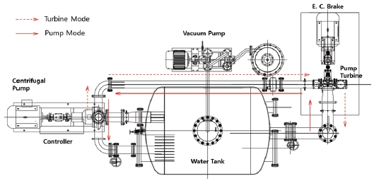
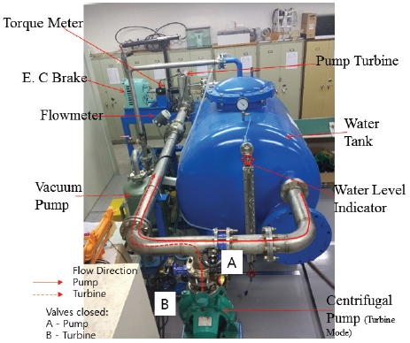
The experiment has been performed in the closed system as shown in Figs. 5 and 6. The experimental setup is mainly focused on the operation of a pump turbine in turbine mode and pump mode. The main parts of the test facility are pump turbine, water tank, pump generator, control valve, flow meter, brake system, motor, pressure transducer, pipe straighteners, electronic control panel, and data logging system. The flow and temperature of the water can be stabilized by using a large size water tank during the facility operation. The water tank is divided into two sections to avoid interfering of inlet and outlet flow. 75% of the water tank is filled with water and remaining with air. The water tank is connected with a vacuum pump to create operation conditions with varying cavitation numbers. The water pump drives the water from the water tank to the pump turbine and offers sufficient head to the pump turbine. The pipe straightener has been used to provide uniform and smooth flow in the pipe to the pump turbine. The flow is returned from the pump turbine to a water tank. Several control valves are situated throughout the experiment facility. These control valves are used to maintain the head and flow rate simultaneously. The electromagnetic flowmeter is located in front of the pump turbine to measure the flow rate. Pressure taps are located at a different location for the measurement of pressure in the pump turbine. The torque and rotational speed of the turbine are measured using the torque transducer, which is placed between the pump turbine and dynamometer. Dynamometer plays the role of an electronic generator in the turbine system. The dynamometer is used to control the torque and rotational speed of the turbine. While controlling the torque and speed, the large amount of heat is produced by the brake, which is mitigated by an air cooling system. While operating in pump mode, the dynamometer was replaced by a motor. However, in the actual pump turbine system, a synchronous motor generator is used.
3.2 Torque meter Calibration
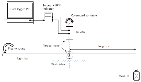
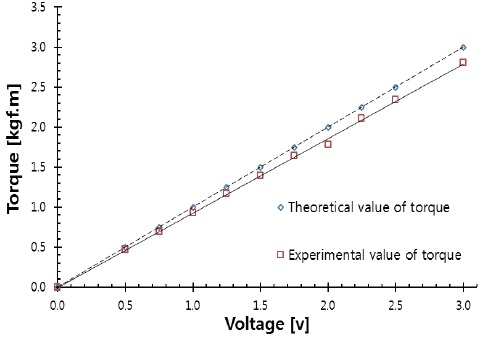
The calibration of the instrument is very important for the measurement. The torque transducer is calibrated for the proper measurement. The swinging arm method has been used for calibration of torque meter, which is illustrated in Fig. 8. In this method swinging arm and variable standard weights were used to capture the readings of torque meter. The standard weight was placed in swinging arm at a known distance to produce torque. The torque produced by the standard weight was measured by torque meter. This obtained value was compared with the theoretical torque according to the corresponding voltage reading on the data logger system. The comparison between the theoretical and experimental torques values is shown in Fig. 9.
The theoretical torque is calculated as follows.
| (7) |
where, τ is the theoretical torque, m is the standard mass, x is the distance between mass and torque transducer.
The difference between the theoretical and experimental value of torque is increasing with increase of the torque. The calibration of the torque will be different with different torque value. When the theoretical torque is high, the difference between theoretical and experimental value of torque is relatively high.
3.3 Error and Uncertainty Analysis
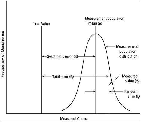
Every measurement has some degree of uncertainty that may arise from different sources. The process of evaluating the uncertainty associated with a measurement result is called error analysis or uncertainty analysis. The error is the difference between the measured value and the actual value. Since the actual value is unknown, the error cannot be known. The total measurement error consists of systematic error and random error as shown in Fig. 9. Systematic errors are reproducible inaccuracies that are consistently in the same direction. These errors are very hard to identify and cannot analyze statistically. Random errors are statistical fluctuations in the measured data due to random sources of error. Fig. 10 shows that systematic error is a constant and random error is vary with repeated measurements(20).
The error analysis and uncertainty analysis has been performed in repeated measurements by evaluating the standard error in the instruments. The mean, standard deviation, uncertainty, and standard error were calculated for the correct estimation of error and uncertainty analysis in the measurement. These quantities are helpful for the prediction of the accuracy and precision of the measuring instruments and technique. The measurement data were obtained from a pump turbine operating in turbine mode.
Table 2 shows the result of the error and uncertainty analysis in measurement. The highest uncertainty is found in the measurement of efficiency. The uncertainty in measurement of efficiency is 3.5%. The standard error for the measurement of head, flow, and torque are 0.003, 0.0055, and 0.0032 respectively. The standard error for the measurement of head is 0.003. The standard error for the measurement of rotational speed and efficiency are 0.16 and 0.15 respectively. The range of error is very small. Therefore, this indicates the precision and accuracy of the measurement is quite reliable.
| (8) |
| (9) |
| (10) |
| (11) |
where, is the mean of the measured data, Xi is the ith measurement data, n=100 is the total number of data, σ is the standard deviation, U is the uncertainty in the measurement, Xmax is the maximum value in the measurement data, Xmin is the minimum value of measurement data, is the standard error in the measurement.
3.4 Mechanical Loss
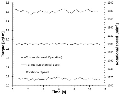
There are many kinds of mechanical losses, but all are not present in the pump turbine system. Friction losses in bearing, stuffing boxes and contact with rotational bodies are the major constituent of the mechanical loss. The mechanical loss in the pump turbine has been measured by the rotating hub shaft at 1800 min-1 without any water supply on the system. Fig. 11 shows the mechanical loss present in the pump turbine system. There is a fluctuation of mechanical loss in the pump turbine system. The average mechanical loss present in the pump turbine system is 0.147 kgfm.
4. Results and Discussion
4.1 Performance Curves
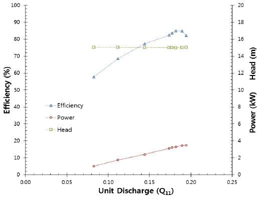
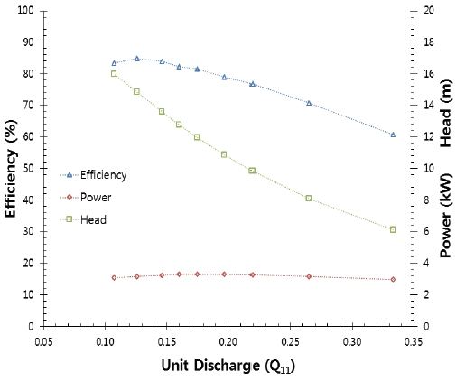
The pump turbine is complicated turbomachinery that works in both the turbine and pump modes. It must satisfy the performance for turbine mode and pump mode simultaneously. The performance of pump mode is affected by the stay vane and guide vane. The pump turbine should achieve the best performance for the turbine mode and pump mode at the same guide vane opening. The performance characteristics of pump turbine have been presented in Figs. 12-13. However, the uncertainty in the measurement of the performance is 3.5%. This indicates that the result of the experiment is precise. The maximum hydraulic efficiency of a pump turbine in the turbine mode is 84.1%, and in pump mode is 84.9%. Considering the small size of impeller, the efficiency of pump turbine is relatively high. The best operating condition for turbine mode is at Q11 is 0.178 and pump mode is at Q11 is 0.127. In turbine mode, the flow rate was maintained by changing the guide vane position.
| (12) |
| (13) |
Where, Q is the flow rate of pump turbine at the outlet, D2 is the outlet diameter of pump turbine in pump mode, H is the effective head of pump turbine, and N is the rotational speed of the pump turbine impeller.
The experiment shows that both turbine mode and pump mode has achieved the operating head of 15m at the best operating condition. The normal operating point for the turbine mode is at Q11 = 0.178, and in the pump mode is at Q11 = 0.104. Pump mode cannot achieve the design head of 15m when Q11 > 0.125. Therefore, pump mode should operate at a range of 0.09 < Q11 < 0.125 for better performance.
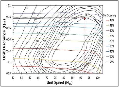
Fig. 14 represents the efficiency hill chart of a pump turbine in the turbine mode. The best efficiency point of the pump turbine in the turbine mode matches the design point. Efficiency for the pump turbine is 84.1% in turbine mode. The efficiency has been normalized in the efficiency hill chart with efficiency at BEP. The hill chart showed that the pump turbine performance is very good in the wide range of rotational speed and flow rate at turbine mode. The experiment shows that the pump turbine can operate in turbine mode from Q11 = 0.17 to 0.19 and N11 = 75 to 95 without compromise in the performance.
As a result of the experiment, the pump turbine shows the relevant performance in turbine mode as well as pump mode. The 3kW power is required by the pump turbine to operate in pump mode. Therefore, renewable sources like solar energy and wind energy can easily operate small scale pump turbine for energy storage. Therefore, pump turbine can store the energy fluctuating energy in off-load period by using pump mode and supply the stable electrical energy in peak load period by using turbine mode. The efficiency hill chart shows that the pump turbine can generate electricity in a wide operating range. Therefore, the combination of renewable energy with the pump turbine is helpful for the production of sustainable energy supply according to the demand.
4.2 Cavitation Performance
Cavitation test in the pump turbine has been conducted in pump mode and turbine mode separately. The vacuum pump was used to create the suction pressure in the pressure tank. The performance of the pump turbine in pump mode and turbine mode has been evaluated in different cavitation number.
| (14) |
| (15) |
Where NPSH is the net positive suction head, σ is cavitation number, pa = 1×10⁵ Pa is atmospheric pressure, pv = 3754 Pa is vapor pressure of water at 25 ˚C, ps is the outlet pressure in turbine mode and inlet pressure in pump mode, H is the net head of the pump turbine. In the experiment vacuum pump was used to decrease the suction pressure of the tank.
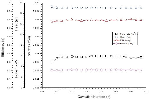
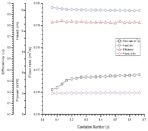
The cavitation test of a pump turbine in turbine mode and pump mode has been evaluated. The drop in the head, flow rate, and efficiency were found by reducing the suction pressure in the pressure tank. The initial decrease in cavitation number has no drastic influence on the performance of the pump turbine. As shown in Figs. 15-16, when Thoma’s cavitation number is less than 0.15, the performance of the pump turbine has decreased. Therefore, the critical cavitation number for the pump turbine is 0.15. There is a 3% efficiency drop in pump mode and turbine mode at σ < 0.15. With a decrease in the cavitation number, the flow rate is also decreasing.
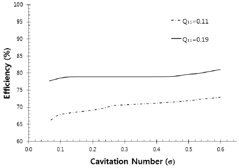
Fig. 17 represents the variation of cavitation performance in partial flow rate and high flow rate. The experiment was carried out by maintaining a constant unit discharge. When Q11 = 0.19, there is 3% efficiency drop for cavitation number, σ = 0.1. However, when Q11 = 0.11, 6% efficiency drop occurred at cavitation number, σ = 0.1. Critical cavitation number is determined by a 3% drop in efficiency. Therefore, the critical cavitation number is different with a different flow rate. The critical cavitation number for Q11 = 0.19 and 0.11 are 0.1 and 0.23, respectively.
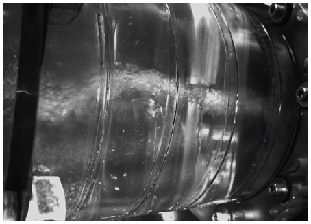
Fig. 18 shows the visualization of cavitation vortex rope in the turbine mode at Q11 = 0.19 and σ = 0.1. The cavitation vortex rope is significantly visible at the critical Thoma’s cavitation number.
5. Conclusion
The study has presented the design and experiment analysis of 3kW class pump turbine for the hybrid system to increase electrical stability for renewable energy sources.
The experimental analysis showed that the efficiency of the pump turbine in the turbine mode and pump mode was 84.1% and 84.9%, respectively. The efficiency of the energy storage system is comparatively very high for the small scale pump turbine system. The efficiency hill chart of the pump turbine in the turbine mode indicates that it can operate in a wide range of operating conditions without affecting performance.
Therefore, the small size pump turbine has the possibility in small scale energy storage system. 3kW power is required to operate the pump turbine in pump mode, which is easily generated by using solar and wind energy. The small size pump turbine can solve the issue of power system management, stability, and quality in renewable energy.
Acknowledgments
This research was supported by research funds of Mokpo National University in 2018.
References
- Renewable Energy, (2018), “Renewable 2018 Global Status Report”, Renewable Energy, Paris.
- SBC, (2011), “SBC energy institute analysis based on US DOE energy storage program planning document”.
- Maharjan, N., Chitrakar, S., and Koirala, R., (2014), “Design of Reversible Pump Turbine for its prospective application in Nepal”, International Journal of Scientific and Research Publications, 4(7), p1-8.
- International Hydropower Association, (2018), “Hydropower Status Report 2018”, International Hydropower Association, London.
- Rastler, D., (2010), “Electricity Energy Storage Technology Options”, Electric Power Research Institute, California.
- Koohli-Kamali, S., Tyagi, V. V., Rahim, N. A., Panwar, N. L., and Mokhils, H., (2013), “Emergence of energy storage technologies as the solution for reliable operation of smart power systems: A review”, Energy Renewable amd Sustainable Reviews, 25, p135-165.
-
Ibrahim, H., Ilinca, A., and Perron, J., (2008), “Energy storage systems- characteristics and comparisons”, Renewable and Sustainable Energy Reviews, 12, p1221-1250.
[https://doi.org/10.1016/j.rser.2007.01.023]

-
Mahlia, T. M. I., Saktisahdan, T. J., Jannifar, A., Hasan, M. H., and Matseelar, H. S. C., (2014), “A review of avilable methods and development on energy storage technology update”, Renewable and Sustainable Energy Reviews, 33, p532-545.
[https://doi.org/10.1016/j.rser.2014.01.068]

- Knapp, R. T., (1934), “Complete characteristics of centrifugal pumps and their use in the prediction of transient behavior”, Transactions of the American Society of Mechanical Engineers, 59(11), p683-689.
-
Jain, S. V., and Patel, R. N., (2014), “Investigations on pump running in turbine mode: A review of the state-of-the-art”, Renewable and Sustainable Energy Reviews, 30, p841-868.
[https://doi.org/10.1016/j.rser.2013.11.030]

- Hasmatuchi, V., (2012), “Hydrodynamics of a Pump-Turbine Operating at Off-Design Conditions in Generating Mode”, Ecole Polytechnique Federale De Lausanne, Suisse.
-
Guggenberger, M., Senn, F., Jaberg, H., Geher, A., Sallaberger, M., and Widmer, C., (2016), “Experimental analysis of the flow pattern of a pump turbine model in pump mode”, in 28th IAHR Symposium on Hydraulic Machinery and Systems, Grenoble.
[https://doi.org/10.1088/1755-1315/49/4/042001]

-
Li, Z. J., Wang, Z. W., and Bi, H. L., (2014), “Numerical study of similarity in prototype and model pumped turbines”, in 27th IAHR Symposium on Hydraulic Machinery and Systems, Montreal.
[https://doi.org/10.1088/1755-1315/22/3/032049]

- Krischner, O., Ruprecht, A., and Riedelbauch, S., (2016), “Dynamic runner forces and pressure fluctuations on the draft tube wall of a model pump turbine”, in 28th IAHR Symposium on Hydraulic Machinery and Systems, Grenoble.
-
Stepanoff, A., (1948), Centrifugal and Axial Flow Pumps, John Wiley & Sons, Inc., New York.
[https://doi.org/10.1016/0016-0032(48)90328-7]

- Kovalev, N. N., (1965), Hydrodynamic design and construction, Israel Program for Scientific Translations, Jerusalem.
- Stelzer, R. S., and Walters, R. N., (1977), Estimating reversible pump-turbine characteristics, US Government Printing Office, Washington.
- Kubota, T., (1997), “Hydraulic Design of Francis Pump Turbine”, in Hydraulic Design of Hydraulic Machinery Ashgate Publishing Limited, Wiltshire, p465-484.
-
Singh, P. M., and Choi, Y. D., (2017), “Initial hydraulic design and performance analysis of 300 MW class pump turbine model”, The KSFM Journal of Fluid Machinery, 20(3), p18-25.
[https://doi.org/10.5293/kfma.2017.20.3.018]

-
Singh, P. M., Chen, Z., and Choi, Y. D., (2017), “Hydraulic design and performance analysis on a small pump turbine system for ocean renewable energy storage system”, Journal of Mechanical Science and Technology, 31(11), p5089-5097.
[https://doi.org/10.1007/s12206-017-1002-7]

- Bell, S., (1999), A Begineer’s Guide to Uncertainty of Measurement, National Physical Laboratory, Middlesex.

